Hi appme
I would start a new thread for circuit discussion, as this thread turns about tube spice models.
How ever, if your circuit is intended to generate an inverted copy of a signal to drive pushpull stages, there are much better/simpler circuits with higher input impedance and less parts needed, like the cathodyn stage, or the long tail PI stage if some gain is needed.
all the best, Adrian
Hi all,
something I have learned the last days is that a tube name is more or less just a convention for a certain mu and gm - and that's all!
(well, ok, also for a certain tube-case/pinout and heater voltage/current, but this is not of interest for spice simulations)
With other words, there are many differences between the same tubes from different manufacturers:
- grid current (especially control grid)
- cut-off behavior (island effect)
- contact voltage (a question of the electrode materials)
- sometimes also the rated plate power
So, that's why I prefer nowadays to generate manufacture-specific tube models!
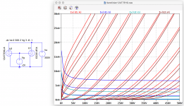
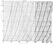
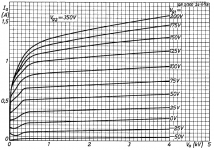
I recently got very good measured data from a 12AT7EHG and a RFT ECC81 (each selected out of 16 triodes for closest match to data sheet) and a you can see in the graph, they are quite different in almost all mentioned properties. Especially between both grid current is more than a factor 2 !!
here the electro-harmonics 12AT7EHG spice model:
...and the spice model for the RFT ECC81:
all the best, Adrian
something I have learned the last days is that a tube name is more or less just a convention for a certain mu and gm - and that's all!
(well, ok, also for a certain tube-case/pinout and heater voltage/current, but this is not of interest for spice simulations)
With other words, there are many differences between the same tubes from different manufacturers:
- grid current (especially control grid)
- cut-off behavior (island effect)
- contact voltage (a question of the electrode materials)
- sometimes also the rated plate power
So, that's why I prefer nowadays to generate manufacture-specific tube models!
I recently got very good measured data from a 12AT7EHG and a RFT ECC81 (each selected out of 16 triodes for closest match to data sheet) and a you can see in the graph, they are quite different in almost all mentioned properties. Especially between both grid current is more than a factor 2 !!
here the electro-harmonics 12AT7EHG spice model:
Code:
*12AT7EHG LTspice model based on the generic triode model from Adrian Immler, version i4
*A version log is at the end of this file
*100h BurnIn of 8 electro-harmonics tubes, sample selection and measurements done in Febr. 2020
*Params fitted to the measured values by Adrian Immler, Febr. 2020
*The high fit quality is presented at adrianimmler.simplesite.com
*History's best of tube decribing art (plus some new ideas) is merged to this new approach.
*@ neg. Vg, Ia accuracy is similar to Koren or Ayumi models.
*@ small neg. Vg, the "Anlauf" current is considered.
*@ pos. Vg, Ig and Ia accuracy is on a unrivaled level.
*This offers new simulation possibilities like bias point setting with MOhm grid resistor,
*Audion radio circuits, low voltage amps, guitar distortion stages or pulsed stages.
*                   anode (plate)
*                   | grid
*                   | | cathode
*                   | | |
.subckt 12AT7EHG.i4 A G K
.params
*Parameters for the space charge current @ Vg <= 0
+ mu   = 63   ;Determines the voltage gain @ constant Ia
+ rad  = 9k5  ;Differential anode resistance, set @ Iad and Vg=0V
+ Vct  = 0.13 ;Offsets the Ia-traces on the Va axis. Electrode material's contact potential
+ kp   = 318  ;Mimics the island effect
+ xs   = 1.5  ;Determines the curve of the Ia traces. Typically between 1.2 and 1.8
*
*Parameters for assigning the space charge current to Ia and Ig @ Vg > 0
+ kB   = 0.25 ;Describes how fast Ia drops to zero when Va approaches zero.
+ radl = 100  ;Differential resistance for the Ia emission limit @ very small Va and Vg > 0
+ tsh  = 8    ;Ia transmission sharpness from 1th to 2nd Ia area. Keep between 3 and 20. Start with 20.
+ xl   = 1.2  ;Exponent for the emission limit
*
*Parameters of the grid-cathode vacuum diode
+ kvdg  = 150 ;virtual vacuumdiode. Causes an Ia reduction @ Ig > 0.
+ kg = 1900   ;Inverse scaling factor for the Va independent part of Ig (caution - interacts with xg!)
+ Vctg = -0.45;Offsets the log Ig-traces on the Vg axis. Electrode material's contact potential
+ xg   = 1.7  ;Determines the curve of the Ig slope versus (positive) Vg and Va >> 0
+ VT   = 0.1  ;Log(Ig) slope @ Vg<0. VT=k/q*Tk (cathodes absolute temp, typically 1150K)
+ Vft2 = -0.1 gft2 = 7  ;finetunes the gridcurrent @ low Va and Vg near zero
*
*Parameters for the caps
+ cag  = 1p6  ;From datasheet ("transfer cap.")
+ cak  = 0p4  ;From datasheet ("output cap.")
+ cgk  = 2p5  ;From datasheet.("input cap")
*
*special purpose parameters
+ os = 1      ;Overall scaling factor, if a user wishes to simulate manufacturing tolerances
*
*Calculated parameters
+ Iad = 100/rad  ;Ia where the anode a.c. resistance is set according to rad.
+ ks = pow(mu/(rad*xs*Iad**(1-1/xs)),-xs) ;Reduces the unwished xs influence to the Ia slope
+ ksnom = pow(mu/(rad*1.5*Iad**(1-1/1.5)),-1.5) ;Sub-equation for calculating Vg0
+ Vg0 = Vct + (Iad*ks)**(1/xs) - (Iad*ksnom)**(2/3) ;Reduces the xs influence to Vct.
+ kl = pow(1/(radl*xl*Ild**(1-1/xl)),-xl) ;Reduces the xl influence to the Ia slope @ small Va
+ Ild = sqrt(radl)*1m ;Current where the Il a.c. resistance is set according to radl.
*
*Space charge current model
Bggi GGi 0 V=v(Gi,K)+Vg0 ;Effective internal grid voltage.
Bahc Ahc 0 V=uramp(v(A,K)) ;Anode voltage, hard cut to zero @ neg. value
Bst   St 0 V=uramp(max(v(GGi)+v(A,K)/(mu), v(A,K)/kp*ln(1+exp(kp*(1/mu+v(GGi)/(1+v(Ahc)))))));Steering volt.
Bs    Ai K I=os/ks*pow(v(St),xs) ;Langmuir-Childs law for the space charge current Is
*
*Anode current limit @ small Va
.func smin(z,y,k) {pow(pow(z+1f, -k)+pow(y+1f, -k), -1/k)} ;Min-function with smooth trans.
Ra  A Ai 1
Bgl Gi A I=min(i(Ra)-smin(1/kl*pow(v(Ahc),xl),i(Ra),tsh),i(Bgvd)*exp(4*v(G,K))) ;Ia emission limit
*
*Grid model
Bvdg G Gi I=1/kvdg*pwrs(v(G,Gi),1.5) ;Reduces the internal effective grid voltage when Ig rises
Rgip G Gi 1G ;avoids some warnings
.func Ivd(Vvd, kvd, xvd, VTvd)  {if(Vvd < 3, 1/kvd*pow(VTvd*xvd*ln(1+exp(Vvd/VTvd/xvd)),xvd), 1/kvd*pow(Vvd, xvd))} ;Vacuum diode function
Bgvd Gi K I=Ivd(v(G,K) + Vctg - uramp(-v(A,K)/mu), kg/os, xg, VT)
.func ft2() {gft2*(1-tanh(3*(v(G,K)+Vft2)))} ;Finetuning-func. improves ig-fit @ Vg near -0.5V, low Va.
Bgr Gi Ai I=ivd(v(GGi),ks/os, xs, 0.8*VT)/(1+ft2()+kB*v(Ahc));Is reflection to grid when Va approaches zero
Bs0 Ai K  I=ivd(v(GGi),ks/os, xs, 0.8*VT)/(1+ft2()) - os/ks*pow(v(GGi),xs) ;Compensates neg Ia @ small Va and Vg near zero
*
*Caps
C1 A G {cag}
C2 A K {cak}
C3 G K {cgk}
.end
*
*Version log
*i1 :Initial version
*i2 :Pin order changed to the more common order „A G K“ (Thanks to Markus Gyger for his tip)
*i3 :bugfix of the Ivd-function: now also usable for larger Vvd
*i4: Rgi replaced by a virtual vacuum diode (better convergence). ft1 deleted (no longer needed)
;2 new prarams for Ig finetuning @ Va and Vg near zero. New emission skaling factor ke for aging etc.
...and the spice model for the RFT ECC81:
Code:
*ECC81 LTspice model based on the generic triode model from Adrian Immler, version i4
*A version log is at the end of this file
*100h BurnIn of 8 RFT tubes, sample selection and measurements done in Febr. 2020
*Params fitted to the measured values by Adrian Immler, Febr. 2020
*The high fit quality is presented at adrianimmler.simplesite.com
*History's best of tube decribing art (plus some new ideas) is merged to this new approach.
*@ neg. Vg, Ia accuracy is similar to Koren or Ayumi models.
*@ small neg. Vg, the "Anlauf" current is considered.
*@ pos. Vg, Ig and Ia accuracy is on a unrivaled level.
*This offers new simulation possibilities like bias point setting with MOhm grid resistor,
*Audion radio circuits, low voltage amps, guitar distortion stages or pulsed stages.
*                  anode (plate)
*                  | grid
*                  | | cathode
*                  | | |
.subckt ECC81.RFi4 A G K
.params
*Parameters for the space charge current @ Vg <= 0
+ mu   = 68   ;Determines the voltage gain @ constant Ia
+ rad  = 9k5  ;Differential anode resistance, set @ Iad and Vg=0V
+ Vct  = 0.28 ;Offsets the Ia-traces on the Va axis. Electrode material's contact potential
+ kp   = 240  ;Mimics the island effect
+ xs   = 1.4  ;Determines the curve of the Ia traces. Typically between 1.2 and 1.8
*
*Parameters for assigning the space charge current to Ia and Ig @ Vg > 0
+ kB   = 0.22 ;Describes how fast Ia drops to zero when Va approaches zero.
+ radl = 520  ;Differential resistance for the Ia emission limit @ very small Va and Vg > 0
+ tsh  = 10   ;Ia transmission sharpness from 1th to 2nd Ia area. Keep between 3 and 20. Start with 20.
+ xl   = 1.3  ;Exponent for the emission limit
*
*Parameters of the grid-cathode vacuum diode
+ kvdg  = 63  ;virtual vacuumdiode. Causes an Ia reduction @ Ig > 0.
+ kg = 840    ;Inverse scaling factor for the Va independent part of Ig (caution - interacts with xg!)
+ Vctg = 0.1    ;Offsets the log Ig-traces on the Vg axis. Electrode material's contact potential
+ xg   = 1.5  ;Determines the curve of the Ig slope versus (positive) Vg and Va >> 0
+ VT   = 0.165 ;Log(Ig) slope @ Vg<0. VT=k/q*Tk (cathodes absolute temp, typically 1150K)
+ kVT=35m ;Va dependant koeff. of VT
+ Vft2 = 0.6 gft2 = 7  ;finetunes the gridcurrent @ low Va and Vg near zero
*
*Parameters for the caps
+ cag  = 1p6  ;From datasheet ("transfer cap.")
+ cak  = 0p2  ;From datasheet ("output cap.")
+ cgk  = 2p3  ;From datasheet.("input cap")
*
*special purpose parameters
+ os = 1      ;Overall scaling factor, if a user wishes to simulate manufacturing tolerances
*
*Calculated parameters
+ Iad = 100/rad  ;Ia where the anode a.c. resistance is set according to rad.
+ ks = pow(mu/(rad*xs*Iad**(1-1/xs)),-xs) ;Reduces the unwished xs influence to the Ia slope
+ ksnom = pow(mu/(rad*1.5*Iad**(1-1/1.5)),-1.5) ;Sub-equation for calculating Vg0
+ Vg0 = Vct + (Iad*ks)**(1/xs) - (Iad*ksnom)**(2/3) ;Reduces the xs influence to Vct.
+ kl = pow(1/(radl*xl*Ild**(1-1/xl)),-xl) ;Reduces the xl influence to the Ia slope @ small Va
+ Ild = sqrt(radl)*1m ;Current where the Il a.c. resistance is set according to radl.
*
*Space charge current model
Bggi GGi 0 V=v(Gi,K)+Vg0 ;Effective internal grid voltage.
Bahc Ahc 0 V=uramp(v(A,K)) ;Anode voltage, hard cut to zero @ neg. value
Bst   St 0 V=uramp(max(v(GGi)+v(A,K)/(mu), v(A,K)/kp*ln(1+exp(kp*(1/mu+v(GGi)/(1+v(Ahc)))))));Steering volt.
Bs    Ai K I=os/ks*pow(v(St),xs) ;Langmuir-Childs law for the space charge current Is
*
*Anode current limit @ small Va
.func smin(z,y,k) {pow(pow(z+1f, -k)+pow(y+1f, -k), -1/k)} ;Min-function with smooth trans.
Ra  A Ai 1
Bgl Gi A I=min(i(Ra)-smin(1/kl*pow(v(Ahc),xl),i(Ra),tsh),i(Bgvd)*exp(4*v(G,K))) ;Ia emission limit
*
*Grid model
Bvdg G Gi I=1/kvdg*pwrs(v(G,Gi),1.5) ;Reduces the internal effective grid voltage when Ig rises
Rgip G Gi 1G ;avoids some warnings
.func fVT() {VT*exp(-kVT*sqrt(v(A,K)))}
.func Ivd(Vvd, kvd, xvd, VTvd)  {if(Vvd < 3, 1/kvd*pow(VTvd*xvd*ln(1+exp(Vvd/VTvd/xvd)),xvd), 1/kvd*pow(Vvd, xvd))} ;Vacuum diode function
*Bgvd Gi K I=Ivd(v(G,K) + Vctg - uramp(-v(A,K)/mu), kg/os, xg, VT)
Bgvd Gi K I=Ivd(v(G,K) + Vctg, kg/os, xg, fVT())
.func ft2() {gft2*(1-tanh(3*(v(G,K)+Vft2)))} ;Finetuning-func. improves ig-fit @ Vg near -0.5V, low Va.
Bgr Gi Ai I=ivd(v(GGi),ks/os, xs, 0.8*fVT())/(1+ft2()+kB*v(Ahc));Is reflection to grid when Va approaches zero
Bs0 Ai K  I=ivd(v(GGi),ks/os, xs, 0.8*fVT())/(1+ft2()) - os/ks*pow(v(GGi),xs) ;Compensates neg Ia @ small Va and Vg near zero
*
*Caps
C1 A G {cag}
C2 A K {cak}
C3 G K {cgk}
.end
*
*Version log
*i1 :Initial version
*i2 :Pin order changed to the more common order „A G K“ (Thanks to Markus Gyger for his tip)
*i3 :bugfix of the Ivd-function: now also usable for larger Vvd
*i4: Rgi replaced by a virtual vacuum diode (better convergence). ft1 deleted (no longer needed)
;2 new prarams for Ig finetuning @ Va and Vg near zero. New emission skaling factor ke for aging etc.
all the best, Adrian
Attachments
Hi AmadeusMozart
That's what I first also thought, you know the story around short and long plate triodes. But I'm no longer convinced that this is the only difference.
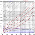
Because if so, all the NOS ECC81/12AT7 would behave identical, but I have found remarkable differences in terms of grid current and also cut-off behavior. See the attached example, comparing the GE 12AT7 with an RFT ECC81.
One may say this is just manufacturing tolerance, but it is not because the RFT is a "golden sample", which means closest to data sheet out of 16 samples.
Another example is the Tesla and Philips PCC88. Their data sheets are quite different regarding cut-off behavior, as an attached graph shows.
But yes, I guess as long as a manufacturer just buyed a construction receipt from another manufacturer (or reverse-engineered it), their tube will behave identical. So actually, a construction-receipt specific spice model would be sufficient. But which self-explaining name should we give for that kind of model?
That's why I hold on to give manufacturer specific spice model names.
all the best, Adrian
That's what I first also thought, you know the story around short and long plate triodes. But I'm no longer convinced that this is the only difference.
Because if so, all the NOS ECC81/12AT7 would behave identical, but I have found remarkable differences in terms of grid current and also cut-off behavior. See the attached example, comparing the GE 12AT7 with an RFT ECC81.
One may say this is just manufacturing tolerance, but it is not because the RFT is a "golden sample", which means closest to data sheet out of 16 samples.
Another example is the Tesla and Philips PCC88. Their data sheets are quite different regarding cut-off behavior, as an attached graph shows.
But yes, I guess as long as a manufacturer just buyed a construction receipt from another manufacturer (or reverse-engineered it), their tube will behave identical. So actually, a construction-receipt specific spice model would be sufficient. But which self-explaining name should we give for that kind of model?
That's why I hold on to give manufacturer specific spice model names.
all the best, Adrian
Attachments
That really gives a different prespective to the datasheets. Likely it is then one explanation that the "golden ears" prefer one brand / tube above others in the same circuit.
It is not unlike the differing opinions on PP versus SE, which imho is more a case prefering head banging output levels or fine nuances.
It is not unlike the differing opinions on PP versus SE, which imho is more a case prefering head banging output levels or fine nuances.
Attachments
Some years ago I was suprised by the manufacturers' differences in datasheet values at the same B+ voltages for the 12AX7/ECC83.
I also came across a document that mentioned different "sound behavior" for the 12AX7 from the different manufacturers.
I also came across a document that mentioned different "sound behavior" for the 12AX7 from the different manufacturers.
Attachments
Dear Adrian,
What you are almost saying is that one should take every tube in the circuit, run it through the curve scanner box to get a graph and then paint a spice model for each individual one using Dmitry N's wonderful piece of software and use the resulting individual spice models to enable one to select component values which dial out all of inaccuracies which exist because we normally only work from a single datasheet graph per tube type.
kind regards
Marek
...yes, Marek, and my holy spice simulation tells me that I should throw away my oscilloscope, as it has obviously measured something wrong!!
But to give you a serious answer:
As long as your triode stage is far away from overdriven situations, you will be happy with a standard spice model.
But if your intention is to design something more complex, where grid current may be an issue, things are different!
E.g. a 12V driven fuzz stage with a triode will sound much different with a electro-harmonix 12AT7EHG than with a RFT ECC81 - and that is something my spice models are able to predict.
all the best, Adrian
People have been selecting "matched pairs" of valves for many years now when building push-pull stages and using a curve tracer to have some idea of performance match along a loadline, rather than just matching current flow at a static test point is quite logical.
The hidden benefits (or newly unhidden benefit) would be that a push pull stage would truly consume a constant current which means power supply capacitors no longer appear in the signal path. I was impressed by Norman Coren's TENA amplifier when he deliberately arranged the first stage and phase splitter loadlines so the change in their current consumption was equal but opposite in sign, with a bias servo on the remainder of the push-pull design. Thus it consumed a constant current, no matter what, and that meant large PSU capacitors simply weren't needed.
kind regards
Marek
Model for 6111
Found a model for the 6111 tube here:
http://adrianimmler.simplesite.com/440956786
Seems quite elaborated
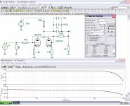
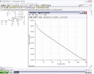
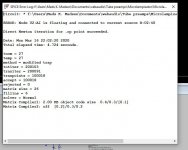
But get the attached error message when using it in a SRPP circuit.
Any thoughts??
No problems when I use the less sophisticated model for 6021 included in ethe .asc file as well
Found a model for the 6111 tube here:
http://adrianimmler.simplesite.com/440956786
Seems quite elaborated
But get the attached error message when using it in a SRPP circuit.
Any thoughts??
No problems when I use the less sophisticated model for 6021 included in ethe .asc file as well
Attachments
Hi Baldin
Thanks for your feedback!
As I found out, my triode i2 models have a weak point. When a high grid current occurs, the i2 version fails to convergence. Such a high grid current may occur, e.g. when a huge cap is parallel to a cathode resistor, and this cap demands high currents to be charged during the startup phase.
Your attached .asc file was not able to be opened with my LTspice IV, so I send you a private message with a quick fixed 6111 model.
May you test for me, if the error disappear with the quick fixed model?
Thanks!
all the best, Adrian
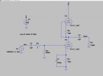
I wasn't able to open the .asc file in post #2215 so I just recreated it as "6111 Test.asc" from the image in post #2219. It ran without errors using Adrian's 6111_i2 model, downloaded from his website. Note that rather than embed the 6111 model in the .asc file I referenced it in an .inc statement (I store my own subcircuit and library files in a "User" folder). Note also that the model is not the "qf" version shown in post #2219 so that could also make a difference.
I've attached both of my files here. Maybe this will help the troubleshooting effort.
I've attached both of my files here. Maybe this will help the troubleshooting effort.
Attachments
Last edited:
- Home
- Amplifiers
- Tubes / Valves
- Vacuum Tube SPICE Models