This is a common problem with all high transconductance tubes. Take a look at the proposed test circuits used with many high transconductance triodes and pentodes. Therein lies the clue..
Most of my new designs use tubes with these issues so I sort my way merrily through them all. I am slowly learning to design circuits that are quite tolerant of this errant behavior..
Types I have seen exhibit this sort of behavior: D3A, 5842, 6688, 7788, C3G, 6Z9P, 6S3P, 6S4P, 6Z52P.. Some are much worse than others, the relatively small sample size 6Z9P (10 pieces) has rather less variation than I expected.
Bear in mind that the curves given in the data sheet are usually the average of many samples, and in practice you are not that likely to get any device that perfectly matches the provided curves although often you will get quite close, and almost as frequently you won't. Small variations in the slope of the transconductance from sample to sample can lead to surprisingly large measured differences tube to tube.
Bear in mind that the curves given in the data sheet are usually the average of many samples, and in practice you are not that likely to get any device that perfectly matches the provided curves although often you will get quite close, and almost as frequently you won't. Small variations in the slope of the transconductance from sample to sample can lead to surprisingly large measured differences tube to tube.
...agree 100%
Vacuum tubes were (back when they had QC) only 20% tolerance devices.
Those data sheet curves were based upon the characteristics of a "bogey" tube, a mathematical, theoretically existing (although some actually exist as "calibration" tubes) tube, where ALL the data was derived from 'averaged' characteristics, not from any single physical tube.
The ONLY way you MIGHT get a tube to replicate the published curves (and then only "close") was if you could find one of the *calibration* tubes--which manufacturers had to "hand pick" from literally thousands of test sample tubes--that were used to calibrate the Tube Tester devices often found in TV repair shops or local drug stores selling replacement radio-TV tubes. Such tubes are VERY hard to find and equally VERY expensive when/if you do find one.
They probably were, but transconductance varies significantly from tube to tube,and the higher transconductance types exhibit greater variations.. Mu in triodes and mu between g1g2 in pentodes is less variable. (Again some high transconductance types if operated over a wide range of Vg can exhibit variable mu - ouch..)
I can believe types like the 6SN7 and 12AX7A match well, types like the 5842 usually are a bit off the mark imle.
I can believe types like the 6SN7 and 12AX7A match well, types like the 5842 usually are a bit off the mark imle.
So why can't each one of us have a relatively inexpensive tube curve tester that can display 'our own' tube characteristics ? Several guys have been trying them out. Isn't it possible to make one with restricted supplies and capabilities that can be useful for the tubes one has and display it on our monitors.
Anyone?
We do, it's called uTracer, and you can build one from scratch or buy the board as a kit here: The uTracer, a miniature Tube Tester / Curve Tracer.
Hi jazbo8,
can you make a spice model for 18040 pentode with Ayumis method, please.
Lack of diagrams is no Ug1 =0 and -0.5 V.
Thank you.
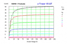
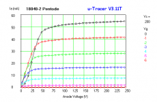
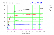
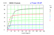
I got my four samples a few days ago, and have traced them as pentodes. I'll curve trace as triodes sometime soon.
Attachments
I got my four samples a few days ago, and have traced them as pentodes. I'll curve trace as triodes sometime soon.
That will be great, although looking at the pentode characteristics, there are pretty large variations already... darn tubes, what'ya gonna do
Good work Kevin. Thank you very much.
Differences in 18040_triode mode likely to be greater. With CCS and LED bias, anode voltage could be even 20% higher.
Maybe (just maybe) constant voltage source (gyrator) is a solution. I do not know, we'll see.
It seems to me that 18040 should be good as a voltage amplifier. Obviously, problem will be matching them.
Happy New year and best wishes to all.
We do, it's called uTracer, and you can build one from scratch or buy the board as a kit here: The uTracer, a miniature Tube Tester / Curve Tracer.
Thanks Kevinkr. That's interesting. Might just build one. Lots of other Links in that website. Plenty to read in the New Year !
Cheers.
Happy New Year to all.


That will be great, although looking at the pentode characteristics, there are pretty large variations already... darn tubes, what'ya gonna do
And there I was thinking they were not too bad.. lol
I have several. I don't know how accurate they are though.Anyone have a LTspice model for the 6S3P please? Searched here and could not find one.
Code:
.SUBCKT 6S3P  1 2 3 ; P G C (Triode) 28-Apr-2006
+ PARAMS: MU= 39  EX= 2.023  KG1= 317.4  KP= 340.73
+ KVB= 400  VCT= 0.0 RGI=1800
+ CCG=6.4P  CGP=2.2P CCP=1.55P
E1 7 0 VALUE=
+{V(1,3)/KP*LN(1+EXP(KP*(1/MU+(V(2,3)+VCT)/SQRT(KVB+V(1,3)*V(1,3)))))}
RE1 7 0 1G
G1 1 3 VALUE={(PWR(V(7),EX)+PWRS(V(7),EX))/KG1}
RCP 1 3 1G    ; TO AVOID FLOATING NODES IN MU-FOLLOWER
C1 2 3 {CCG}  ; CATHODE-GRID;
C2 2 1 {CGP}  ; GRID-PLATE;
C3 1 3 {CCP}  ; CATHODE-PLATE;
D3 5 3 DX     ; FOR GRID CURRENT
R1 2 5 {RGI}  ; FOR GRID CURRENT
.MODEL DX D(IS=1N RS=1 CJO=10PF TT=1N)
.ENDS
Code:
.SUBCKT 6S3P  1 2 3 ; P G C (Triode) 27-Dec-2006 by GaLeX
+ PARAMS: MU= 54.1  EX= 2.828  KG1=405  KP= 170
+ KVB= 150   VCT=  0  RGI=1000
+ CCG=6.9P  CGP=1.65P CCP=2P
E1 7 0 VALUE=
+{V(1,3)/KP*LN(1+EXP(KP*(1/MU+(V(2,3)+VCT)/SQRT(KVB+V(1,3)*V(1,3)))))}
RE1 7 0 1G
G1 1 3 VALUE={(PWR(V(7),EX)+PWRS(V(7),EX))/KG1}
RCP 1 3 1G    ;
C1 2 3 {CCG}  ;
C2 2 1 {CGP}  ;
C3 1 3 {CCP}  ;
D3 5 3 DX     ;
R1 2 5 {RGI}  ;
.MODEL DX D(IS=1N RS=1 CJO=10PF TT=1N)
.ENDS
Code:
.SUBCKT 6S3P-EV 1 2 3 ; P G C (Triode) 21-Sep-2007 by oleg_s
+ PARAMS: MU= 50.05 EX= 2.73 KG1=520.29 KP=1378.63
+ KVB=1378.63 VCT=0.00 RGI=1000
+ CCG=6.7P CGP=2.4P CCP=1.65P
E1 7 0 VALUE={V(1,3)/KP*LN(1+EXP(KP*(1/MU+(V(2,3)+VCT)/SQRT(KVB+V(1,3)*V(1,3)))))}
RE1 7 0 1G
G1 1 3 VALUE={(PWR(V(7),EX)+PWRS(V(7),EX))/KG1}
RCP 1 3 1G ;
C1 2 3 {CCG} ;
C2 2 1 {CGP} ;
C3 1 3 {CCP} ;
D3 5 3 DX ;
R1 2 5 {RGI} ;
.MODEL DX D(IS=1N RS=1 CJO=10PF TT=1N)
.ENDSHow do each of those three different models plot out? Similar, close, or "...no cigars..."?
I just tried the last one because the mu value seems close to the data sheet value. Certainly as far as dc operating point is concerned I set it up for 1mA quiescent and 100V on the plate in a CC and the datasheet Vgc was obtained.
Thanks for the fast response and the choice of models.
Cheers
Ian
Here's a 6S3PE model I just traced using Curve Captor. Seems to follow the published curves fairly well.
Code:
* 6S3PE LTSpice model
* Modified Koren model (8 parameters): mean fit error 0.224602mA
* Traced by Wayne Clay on 1/5/2014 using Curve Captor v0.9.1
* from Soviet 6S3PE data sheet
* URL: http://tubedata.milbert.com/sheets/113/6/6S3PE.pdf
.subckt 6S3PE  P G K
    Bp  P K  I=
+ (0.0001606951761m)*uramp(V(P,K)*ln(1.0+(-0.5719608703)+exp((0.9117147739)+
+ (0.9117147739)*((70.72155169)+(349.9324992m)*V(G,K))*V(G,K)/sqrt((1.186403557e-005)**2+
+ (V(P,K)-(4.242359953))**2)))/(0.9117147739))**(2.475026509)
  Cgp G P 2.4p ; 0.2p added
  Cgk G K 7.6p ; 0.7p added
  Cpk P K 2.35p ; 0.7p added
  Rpk P K 1G ; to avoid floating nodes
  d3  G K dx1
.model dx1 d(is=1n rs=2k cjo=1pf N=1.5 tt=1n)
.ends 6S3PE- Home
- Amplifiers
- Tubes / Valves
- Vacuum Tube SPICE Models