the UL84 is the tube for you, 100mA heater........Neat tube. Thanks, now I've got another to add to the list.
The UL84 is NOT a 45 volt heater version of the EL84. It is a 45 volt, 100 mA version of the 6CW5 / EL86 tube. It is relatively easy to squeeze 25 to 30 watts from a P-P pair without red plate. Data sheet shows 25 watts from a pair with a 3K ohm load, 200 volts G2, and 250 volts plate.
RESPECT the 200 volt screen rating. Merely plugging these into an EL84 circuit will result in a rapid meltdown.
The plate voltage rating can however be violated at will, after all it is the same plate as found in the EL84. Keep the screen in the 180 to 220 volt range and use a higher plate load impedance as the plate voltage is raised. I have been to 430 volts into a 6600 ohm load, resulting in over 30 watts of output.
I made a guitar amp using a series heater string with some 26AQ6 / UCC85's for preamp tubes. It ran from a 340 volt supply with 170 volts on G2 and cranked out about 27 watts using a mains / line voltage toroid for the OPT. Power was derived from a voltage doubler on an isolation transformer.
Last edited:
The UL84 is NOT a 45 volt heater version of the EL84. It is a 45 volt, 100 mA version of the 6CW5 / EL86 tube. It is relatively easy to squeeze 25 to 30 watts from a P-P pair without red plate. Data sheet shows 25 watts from a pair with a 3K ohm load, 200 volts G2, and 250 volts plate.
RESPECT the 200 volt screen rating. Merely plugging these into an EL84 circuit will result in a rapid meltdown.
The plate voltage rating can however be violated at will, after all it is the same plate as found in the EL84. Keep the screen in the 180 to 220 volt range and use a higher plate load impedance as the plate voltage is raised. I have been to 430 volts into a 6600 ohm load, resulting in over 30 watts of output.
I made a guitar amp using a series heater string with some 26AQ6 / UCC85's for preamp tubes. It ran from a 340 volt supply with 170 volts on G2 and cranked out about 27 watts using a mains / line voltage toroid for the OPT. Power was derived from a voltage doubler on an isolation transformer.
Interesting...
I do have a pair of 6k 30 watt transformers, and an extra isolation transformer...
Looking on eBay, apparently the PL84 can still be had for around a dollar, looks like a good tube to stock up on. The UL84 looks like you could series-string the heaters off of CCS and run it off of the raw screen supply, and still only a couple bucks each... design the circuit with an adjustable screen supply and you could fairly quickly go with the EL84 later on.
Like I said, neat tubes. I'll have to grab a few quads to mess with. Maybe regulate G2 with some VR tubes and a source follower...
Last edited:
I'm not considering any tubes that are difficult to find for the finals in my amp - plain vanilla all the way. I have several flavors of 6L6GC and some EH KT88s that will do just fine.
Anything over 10W or so will be P-P rather than SE. Again, plain vanilla tubes (6L6GC or 7591A) will get me a comfortable 30W/channel or so with a 400V B+.
The extra chocolate sauce and sprinkles will be the circuitry that surrounds the otherwise proletarian tubes...
Hard to beat the 6L6GC, it is a very versatile and easy to build around tube. Go A2/AB2 and rock on!
My go-to lower power tube is the 6V6, easy to find, reasonably easy to drive, and affordable.
The UL84 looks like you could series-string the heaters off of CCS and run it off of the raw screen supply
Enclosed is the PDF of the Eagle schematic for the board I laid out for this test amp. It is a guitar amp that I designed for the Hundred Buck Amp Challenge several years ago. I tend to throw everything on the initial PC board design and rip out or populate what I want at build time. Then, after hacking it up and making what I really want out of it, I'll lay out a new board.
The preamp section was found to have way too much gain, and therefore got hacked up a lot, the mosfet followers were ripped out except for Q3 and Q7 which drive a pot. The mosfets in series with the cathode bypasses got lost too. The power supply and power amplifier worked great from first power up so they remain.
The amp got lost when I had to move twice in a year on short notice, but it will be explored further when I find it.
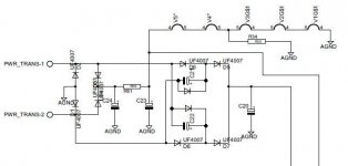
Power supply:
The power transformer is a 100 VA isolation transformer with a 120 volt secondary. The typical Triad N68-X ran too hot feeding this amp since all of the current is drawn in short pulses.
Diodes D1 through D4 form a conventional FW bridge with about 170 volts (on my 122 volt line) across C23. This feeds the 168 volt series heater string and the output tube's screen grids directly. R34 was added so I could experiment with 150 mA output tubes. Those experiments never happened since the UL84's exceeded my expectations.
Diodes D5 through D8 form a FW voltage doubler delivering about 340 volts at idle, with some sag when the amp is blasted well into clipping. The rest of the amp runs from this supply in a manner similar to most guitar amps, but patterned after the "Marshall 18 watt" design.
Attachments
Don't forget, the PL84 and UL84 differ only by heater, they are both not like a EL84.
The voltage doubler has a possible problem.If C21 and/or C22 are smaller than C20 they get charge in the wrong direction.To prevent damage best put diodes across.The final voltage is reached faster too.
Mona
The voltage doubler has a possible problem.If C21 and/or C22 are smaller than C20 they get charge in the wrong direction.To prevent damage best put diodes across.The final voltage is reached faster too.
Mona
Attachments
The trek continues - one side of the amp biases up ok sans output transformer, and the final on the other side shows no current whatsoever. I suspect a bad socket contact, as voltages otherwise look all right, and will investigate and/or replace. I also used a thermal camera to look at resistor temperatures, and will be doubling up on resistors in places where the temperatures exceed 100C.
I may go to standard sockets with flexible interconnects to PCB rather than put up with substandard PCB sockets, as I have had problems with the 9-pin PCB sockets as well. A bonus is that this approach takes the stress off the PCB when tubes are pulled/replaced.
I may go to standard sockets with flexible interconnects to PCB rather than put up with substandard PCB sockets, as I have had problems with the 9-pin PCB sockets as well. A bonus is that this approach takes the stress off the PCB when tubes are pulled/replaced.
Wow, I managed to dig out my pair of Transcendar TT-312-OT (5k, 10W, UL tap) from the pile in the basement, so this project may actually get finished some time in the hazy, distant future. Once I get the biasing issues sorted with the power amp, I'll try to make it play running off bench supplies.
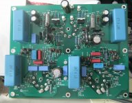
I've been busy populating the lineamp portion of the board shown in post #32, a variant of a lineamp concept shown in the "evil sandman" thread. The variant in question makes it possible to adapt a lineamp to a variety of tubes without a lot 0f shilly-shallying around, at the cost of some electrolytic caps in places where I normally don't want to see them. Simulation results are excellent. Listening results, as usual, are another question. Hold on to your hats...
Here is the latest RIAA preamp plus lineamp module mostly stuffed. The lineamp section biased up sweetly first time around last night, with reasonable device temperatures. Signal testing will follow shortly.
I'll then concentrate on the RIAA section. I may chhange theRIAA section to a folded cascode design that will have more optimum tube bias currents, plus the capability of operating at 150V rather than 200V B+ with some overload margin.
I'll then concentrate on the RIAA section. I may chhange theRIAA section to a folded cascode design that will have more optimum tube bias currents, plus the capability of operating at 150V rather than 200V B+ with some overload margin.
Attachments
Well, I got both output stages of the power amp module up and running -- the problem was an open screen stopper resistor connection. Once that was soldered, both output stages took off and biased ok. This is a graphic illustration of the fact that screen voltage is crucial in setting plate current for pentodes/beam tetrodes - no screen voltage, no plate current.
The bias currents on the pentode input stages are grossly mismatched (screen voltages are almost identical, to within 0.5V), so that's my next demon to wrestle. I'll try switching input tubes first to see if the problem follows the tube. I hope not...
The bias currents on the pentode input stages are grossly mismatched (screen voltages are almost identical, to within 0.5V), so that's my next demon to wrestle. I'll try switching input tubes first to see if the problem follows the tube. I hope not...
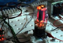
Swapping out the input tube with weak bias cured the input bias imbalance problem. The amp carcass can now come home to be fleshed out with interconnects and output trannies. I'll also be looking for output tubes with blue envelope glow. I'm currently running a used pair of Ruby branded Chinese 6L6GC outputs - no glow...
I'm not doing a "Full George" - only 24W, and screen is set at 350V.
I have a fair number of 6L6GCs hanging around, mostly Chinese and Russkie, with a few used JJs. I like the shape of the JJs, but I don't like their reliability reputation. Some of the EH tubes I have sit a bit ****-eyed on the base - maybe that was why the seller let them go for cheap,,,
The plate voltage is only 400V, so I might not get all that much glow, even if I find some likely prospects.
That one was eating about 40 watts at the time. I have had that pair since I pulled them out of a Fender Bandmaster because the owner wanted something different. That was about 8 years ago. Despite many trips into the red zone, they are still alive. I use them to test new ideas that might not go exactly as planned.
My Rubys are straight-sided rather than coke bottle.
I have a bunch of Chinese no-brands in both straight and coke bottle, as well as a quad of straights that are Mesa branded, but look the same as the unbranded. I would hesitate to push any of these over the GB 19W plate rating, as the innards are on the smallish side. The Rubys are more generously proportioned.
I have a bunch of Chinese no-brands in both straight and coke bottle, as well as a quad of straights that are Mesa branded, but look the same as the unbranded. I would hesitate to push any of these over the GB 19W plate rating, as the innards are on the smallish side. The Rubys are more generously proportioned.
I am using the power section of this amp as a test bed for a concept of powering the amp with a DC-DC converter running off of a high power switching adapter, moving the nasty AC interface off chassis , along with a third of the weight. I went from a Millett-type E-linear circuit to a more standard partial feedback approach so I could run the tube screens at 200V and make biasing easier. Right now the output tubes are 6L6GC with about 420V plate voltage, and ~ 53 ma bias. This will give me a little under 7W RMS/channel.
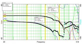
THe big problem in this whole effort is dealing with the ragged frequency response of the Transcendar output transformers. I have had to use fairly drastic measures to get them to shut up, while at the same time getting even marginally acceptable closed loop response. Having access to a gain-phase analyzer lets me see all the ugly warts associated with a given piece of output iron
I used Millett's method of a capacitor from the plate of the input pentode to ground in order to smooth out the frequency response some. Making that capacitor an RC network gave me increased closed-loop phase margin. Using aggressive closed loop compensation allowed me to cross 0dB with acceptable phase margin, at the cost of chewing up my 20k response.
The attached gain-phase plot shows both the open loop response of the partial feedback amp without global feedback (red and blue curves), as well as the closed loop response (black curves) .The amp is stable as evidenced by both the gain-phase plots and the square wave response, but the bandwidth is certainly nothing to write home about.
If I drag this monstrosity to this year's Burning Amp, it will be as an advanced breadboard screwed to a piece of lumber, powered by the switching adapter and DC-DC converter. I don't want to go to the trouble of mounting the amp into a case until I can get my hands on some more decent output iron and clean up the frequency response. I may try the One Electron 4.8k transformers next. Once I get some decent gain-phase results, I would like to try the exercise of dropping in a pair of KT88 outputs and going for an honest 10W RMS/channel. My DC-DC converter will support that level of power.
Attachments
Last edited:
Hmmmm - I don't think I have any One Electron UBT-2s in house, but I do have a pair of the 3k UBT-3s. These would deliver 10W per channel with KT88 outputs biased at about 85 ma, within the plate dissipation limit for that beast, especially as I will be babying the screens at only 200V. The big question is whether the partial feedback synthesized triode will be low enough impedance to be a good match for the transformers.
It won't hurt to just try it, as I already have the iron in hand - after Burning Amp, though, as I already have a full plate.
It won't hurt to just try it, as I already have the iron in hand - after Burning Amp, though, as I already have a full plate.
- Status
- This old topic is closed. If you want to reopen this topic, contact a moderator using the "Report Post" button.
- Home
- Amplifiers
- Tubes / Valves
- Tube Integrated Amp