Hi,
I had just bought a 6n3 x2 tubes and 6Z4 tube SRPP pre-amp kit.
I am in the process of running them in.
As the tube sockets came soldered onto the PCB board, I would like to find out what type of cables are suitable for use if i decides to mount the Tube sockets onto a chassis.
Would the it sound better if I change the 6N3 tubes (china) to it's western equivalent?
Thank you for your precious advice.
Hi,
For my projects I use ordinary common available switchgear/ equipment wire.
I came across of a large number of these wires in different sizes and colours when the city of Hamburg modernized their telephone equipment and cleared the warehouses from now obselete spare parts. That was way back in 1991.
The size of the wires depends on the expected current. AWG 17/18 0.75 mm² for mains/ heater circuits , AWG 23 /24/ 0.3 mm² for signal pathes. In some cases screened wires. Safety grounds / Earth are always AWG 16 1.5 mm²
I prefer wires with solid conductors as I have.
I always pull spaghetti over mains wires to improve the safety of the circuits. We got 230V mains voltage here.
73
Wolfgang
I would like to find out what type of cables are suitable for use if i decides to mount the Tube sockets onto a chassis.
For my projects I use ordinary common available switchgear/ equipment wire.
I came across of a large number of these wires in different sizes and colours when the city of Hamburg modernized their telephone equipment and cleared the warehouses from now obselete spare parts. That was way back in 1991.
The size of the wires depends on the expected current. AWG 17/18 0.75 mm² for mains/ heater circuits , AWG 23 /24/ 0.3 mm² for signal pathes. In some cases screened wires. Safety grounds / Earth are always AWG 16 1.5 mm²
I prefer wires with solid conductors as I have.
I always pull spaghetti over mains wires to improve the safety of the circuits. We got 230V mains voltage here.
73
Wolfgang
On the studio gear I make:
I use primarily 587 wh005 alpha wire. I'll use also the solid 20ga version thite pfte wire) then I jacket with fiberglass sleeve (comes in white then I spray paint it with engine paint lightly with what ever color I want),
I also like the cloth sleeve wire at tubesandmore.com for my vintage repairs and new guitar amp builds.
Good suggestions were made by the previous posters. Another useful option is silver plated copper wire, with "Kynar" insulation. That stuff is is used for wrapped connections and works very well, when soldered into place.
Plenty of suitable, solid core, wire in the 22 to 24 AWG size is available. Use something decent that you can obtain locally and whose price is relatively favorable.
Plenty of suitable, solid core, wire in the 22 to 24 AWG size is available. Use something decent that you can obtain locally and whose price is relatively favorable.
Thank you all for advice, as far as I know the 6N3 tubes are primarily for signal (pls forgive me for my ignorance) should I use good signal cable for the signal path and thicker cable for the electrical path? The 6Z4 is primarily a rectifier tube which provides power, what type or size is recommended for it's purpose.
Use the preamp, as is, for a while. Get to know what its strengths and weaknesses are. Then, you can try "rolling" tubes. Make only 1 change at a time.
Unless the stuff that came with the kit is utter garbage, wire is (IMO) way down on the list of things to tweak. For instance, Chinese electrolytic capacitors are not well thought of. Replacement of the kit's 'lytics by Panasonic or Nichicon 105o C., low impedance, parts is a possible modification.
Unless the stuff that came with the kit is utter garbage, wire is (IMO) way down on the list of things to tweak. For instance, Chinese electrolytic capacitors are not well thought of. Replacement of the kit's 'lytics by Panasonic or Nichicon 105o C., low impedance, parts is a possible modification.
the original 5Z4 were metal types, i still have several american made tubes,
the Chinese used a shouldered tube in their current production 5z4's....
5Z4 @ The National Valve Museum
btw, i also worked in Singapore from 1997 till 2000 working in Pulao Sakra....i stayed in Clementi...
the Chinese used a shouldered tube in their current production 5z4's....
5Z4 @ The National Valve Museum
btw, i also worked in Singapore from 1997 till 2000 working in Pulao Sakra....i stayed in Clementi...
Wiring example
Hi folks,
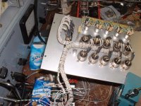
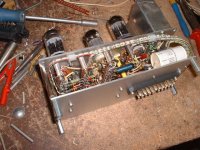
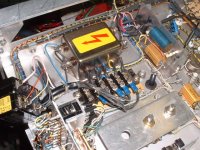
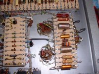
here an example of some kinds of wiring I done with ordinary switchgear wire.
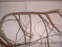
The first both pics showing the input panel and the line driver of my homebrew pre-amp. The third pic show the harness of the line driver stage. The both right ones are showing the wiring in my MC-3500 power amp clones.
73
Wolfgang
Hi folks,
here an example of some kinds of wiring I done with ordinary switchgear wire.
The first both pics showing the input panel and the line driver of my homebrew pre-amp. The third pic show the harness of the line driver stage. The both right ones are showing the wiring in my MC-3500 power amp clones.
73
Wolfgang
Attachments
Such neat wiring can be a pig to debug/fault-trace, and can encourage coupling between different circuits. I do my best to avoid it!
Hi DF96,
yes it could, but I spent lot of effort to avoid it , because I personally like this way of wiring. My invested time to finish such kind of equipment is not an issue. I made drawings of the wiring and give all wires a running number. In case of a fault its easy to trace each single wire vom its start its destiny. In several projects I had to make one or the other cable harness twice, because of a false running wire. But most of these bundles contains only supply , ground, heater , control or balanced audio wires.
I never put high impedeance wires into my cable looms. For other sensitive wires with lower impedance I take screened ones . In the added pics of my previous page there are lot of balanced circuits, which will not an issue for coupling high frequency loss.
I worked in a company way back in the seventies. This Firm produced equipment for german brodcasting and the post office telecom in small quantities. We did the wiring in the same way, without any troble at all.
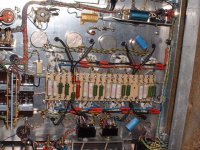
Here are another sample of how I made it. You see that the plate wires run separate from the harness (the black sleeve left of the valve sockets), the heater wires are screened avoid spreading mains hum into the circuit. These pics showing the interior of a 10W Guitar amp I build a while ago.
73
Wolfgang
Attachments
Hi all,
I will really appreciates your input as I this is my first attempt on the simple pre-amp.
in the diagram below
https://dl.dropboxusercontent.com/u/96460339/Philips Caps.jpg
Thanks in advance for all your great inputs!!!
I will really appreciates your input as I this is my first attempt on the simple pre-amp.
in the diagram below
An externally hosted image should be here but it was not working when we last tested it.
https://dl.dropboxusercontent.com/u/96460339/Philips Caps.jpg
Thanks in advance for all your great inputs!!!
- Status
- This old topic is closed. If you want to reopen this topic, contact a moderator using the "Report Post" button.
- Home
- Amplifiers
- Tubes / Valves
- Correct wiring types