Why A2 with a horn/Onken system? You gotta have more than enough efficiency. IMHO, allowing an SE into A2 kinda defeats the purpose of Class A to begin with. (Yeah, I know it's only for the those "last few" watts, but I swear I can hear it)....I'd employ fixed bias and make every effort to minimize primary and secondary DCR is this case for excursions well in A2 territory. (40W + out of a GM70 into 5K at 1.1kV)
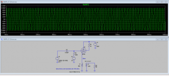
Here is something relevant to the thread. This is a transformer coupled CF driver for a GM70, not too different from the circuit I discussed previously.
The intention is to allow for A2 operation, the 5K load resistor is to demonstrate performance at 20mA out. Feedback around the whole driver stage might be advisable to help correct amplitude errors (essentially unintended compression due to the finite source impedance of the CF and the transformer DCR) as the load impedance goes from essentially infinite to something rather lower.
The intention is to allow for A2 operation, the 5K load resistor is to demonstrate performance at 20mA out. Feedback around the whole driver stage might be advisable to help correct amplitude errors (essentially unintended compression due to the finite source impedance of the CF and the transformer DCR) as the load impedance goes from essentially infinite to something rather lower.
Attachments
Why A2 with a horn/Onken system? You gotta have more than enough efficiency. IMHO, allowing an SE into A2 kinda defeats the purpose of Class A to begin with. (Yeah, I know it's only for the those "last few" watts, but I swear I can hear it).
Mine is designed only for class A1 operation, this is a different discussion stemming from the original tinnitus Broskie CF post. Also mine are long finished. (minor driver revisions are planned eventually)
My mistake.Mine is designed only for class A1 operation, this is a different discussion stemming from the original tinnitus Broskie CF post.
Still, other than the Broskie circuit, (which I thought was introduced more or less as an intellectual exercise), what indications do we have that A2 is an intended target?
My mistake.
Still, other than the Broskie circuit, (which I thought was introduced more or less as an intellectual exercise), what indications do we have that A2 is an intended target?
We don't, it was a branch prompted by Tinnitus' post on the Broskie CF, it was also an intellectual exercise to illustrate how this circuit might be employed in a GM70 amplifier design.
and a good one too....it was also an intellectual exercise to illustrate how this circuit might be employed in a GM70 amplifier design.
Kudos to you for the circuit and the SPICE sim.
I wonder what yagoolar has in mind.
As long as we're IT-coupling, why not a beam triode such as 6HZ5? Plenty of current, plenty of gain, plenty of swing. Price/performance ratio should be high and ease of implementation (aside from its duodecar socket) is up there, too – (could be run off the same B+ as the '70).
The idea with the 6HZ5 is actually done by Thomas Mayer, member here. I think that the hard part is indeed the output stage around the GM70: the high voltage, the big/expensive OPT, the 60W filament... once that is accomplished, there is probably a thousand possibilities to drive it...
and a good one too.
Kudos to you for the circuit and the SPICE sim.
I wonder what yagoolar has in mind.
As long as we're IT-coupling, why not a beam triode such as 6HZ5? Plenty of current, plenty of gain, plenty of swing. Price/performance ratio should be high and ease of implementation (aside from its duodecar socket) is up there, too – (could be run off the same B+ as the '70).
The problem with the 6HZ5 is that I understand that it has a rather high rp which would tend to drive up the cost of the IT significantly - which already are not inexpensive for good ones.
I'm using the LL1635/20mA in my amplifier driven by a triode connected D3A. (rp <2K) These are reasonably priced ($120 each) and perform a lot better than I expected. Significantly better performance will cost a lot more, noting I did not know what to expect when I designed these amps so I wanted to limit my exposure in the event their performance was disappointing which is why I also went to Electra-Print for the outputs and Edcor for power which are both highly cost effective choices. I've had no inclination to revisit those choices so far, although perhaps I could eventually get a better custom IT from monolith magnetics. (lower dcr, more inductance, higher perm core)
and a good one too.
Kudos to you for the circuit and the SPICE sim.
I wonder what yagoolar has in mind.
[...]
I've been considering three tubes as the first stage:
- C3g triode strapped
- 6C45pi
- E180f
From aestethical point of view, however, I wish a tube were bigger than C3g. Closer to 6L6 in size
I assume a buffer may be neccessary to use for driving GM70.
For time being I am not thinking about IT as I don't own one.
Last edited:
True, and you need a decent step-down ratio. Although, you might save the differenceThe problem with the 6HZ5 is that I understand that it has a rather high rp which would tend to drive up the cost of the IT significantly - which already are not inexpensive for good ones.
(in $ you spend on an IT) by not having more than one HT supply.
Understood.I've been considering three tubes as the first stage:
- C3g triode strapped
- 6C45pi
- E180f
From aestethical point of view, however, I wish a tube were bigger than C3g. Closer to 6L6 in size
I assume a buffer may be neccessary to use for driving GM70.
For time being I am not thinking about IT as I don't own one.
So, 2 or 3 stage? (and do we care about being able to get to A2?)
Also, what kind of input sensitivity do you need?
Other candidates you might consider:
- 6Н6П
- 6Н30П/6Н30П-ДР
- D3a
- 6AU5
- 6SN7/12SN7
- 6Э5П triode
- 826
Last edited:
I recommend a two stage topology if possible unless A2 operation is required for the extra power output. I've found that additional complexity usually results in a loss of resolution. A high mu triode or triode strapped pentode with high mu (I used D3A) loaded by a choke or CCS should give you sufficient sensitivity.
I recommend a two stage topology if possible unless A2 operation is required for the extra power output. I've found that additional complexity usually results in a loss of resolution.
I strongly agree with Kevin in this regard
Ditto. You could get to A2 in a 2-stage parafeed, but I'd concentrate on a first-rate A1 design.I strongly agree with Kevin in this regard
I have chosen those because ... they have been eagerly waiting to be usedDitto. You could get to A2 in a 2-stage parafeed, but I'd concentrate on a first-rate A1 design.
") Why not use elements I have?
Why not use elements I have?I already implemented* E180f triode strapped with a CCS driving 6C4C parafeed. The results were more than satisfying.
6H6 or 6H30 don't have enough gain as a single stage, AFAIR.
I read about 6Э5П - will consider it too.
____
* I don't know if "implement" is a good verb here, be me-IT-guy, so I beg your pardon.
A good choice – I've run them on 6080 and 12B4 before and like 'em – (I've never tried them w/a '70)....I already implemented E180f triode strapped...
It depends on what you need for sensitivity.6H6 or 6H30 don't have enough gain as a single stage, AFAIR.
The advantage they have is that, using a 300-350V supply stacked "under" B+, you can DC couple without an IT or a cap – (the voltages just "line up" perfectly).
The disadvantage is that, unless you're using an active preamp, you need to use a 1:2 or 1:4 input trafo; (I didn't mind 'cause I also wanted balanced in, so...)
That's a surprisingly good tube (triode-strapped); and also keeps things "all Russian" (if you care).I read about 6Э5П - will consider it too.
- Status
- This old topic is closed. If you want to reopen this topic, contact a moderator using the "Report Post" button.
- Home
- Amplifiers
- Tubes / Valves
- Winter is coming... Time to start GM70 SE parafeed amp