thank you all guys!!!
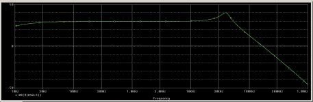
at the end the solution is RC 33k+22pF between the anode of the 12AX7.
the anode load is 220k cos' tryin in lab showed a little less distortion.
all the amp now is stable even without load.
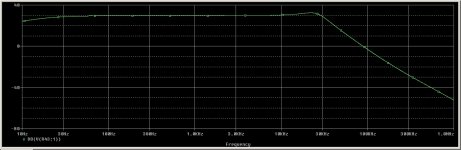
from the simulation I've done, this RC network lower the peak situated at about 30kHz, it depends from the parastic capacitance of the transformer (that I don't know), I've supposed 100pF...
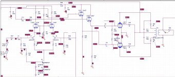
for tube mania: the yellow cable is the bias, look at the pcb I've attached in first post, the star grounding is correct.
at the end the solution is RC 33k+22pF between the anode of the 12AX7.
the anode load is 220k cos' tryin in lab showed a little less distortion.
all the amp now is stable even without load.
from the simulation I've done, this RC network lower the peak situated at about 30kHz, it depends from the parastic capacitance of the transformer (that I don't know), I've supposed 100pF...
for tube mania: the yellow cable is the bias, look at the pcb I've attached in first post, the star grounding is correct.
Attachments
I didn't mean yellow...I trying to tell you that the cathodes should be groundet to your earth point with the yellow/green cable tied to it. Its always good to give the output tubes there own leed to ground and closest possibly to starground/rectifier. However if it works now...forget it.
Last edited:
One of my buttons has been pushed: giving things the correct name.
Not a Zobel: Zobels are at amp outputs, to isolate the output stage from load capacitance at RF frequencies.
It is a lead-lag compensation network, to stabilise the feedback loop at ultrasonic frequenicies. Different purpose, different frequency range, different design procedure, different name. Whether 1/10th of the anode load resistor is about right depends on the relationship between the anode load resistor and the anode impedance, which depends on triode or pentode and whether cathode degeneration has been used.
Zobel network - Wikipedia, the free encyclopedia
Seems we are both wrong - ar!! well it happens.
luixssj3 - glab you got it sorted.
Cheers,
Ian
Er .... well then ....
I read up the Zobel explanation; most informative.
But when going to Boucherot's work, it says that his 'cell' was rather aimed at compensating for a specific frequency (inductive motors and such), and that in that sense, the output R.C in amplifiers might as well be called a Zobel network since the application there was wide-band .....
What about a Zoberot or perhaps a Bouchebel network??
Luixssj3,
Hate myself for doing this ...
but perhaps you can just check the operating points of the 12AX7 triodes. On my plate graphs for 12AX7, you come awfully close to zero-bias point and grid current on the down swing of the plates - also including possible spread of the fets. Do they have to work at all of 35V? Perhaps going down somewhat on G1 (common) voltage, thus increasing Va-k to over 100V. One way to test is to over-drive slightly and see how close to increased distortion/bottoming on the 12AX7 plate swing you are. (The extra cathode voltage on the 12AU7 should not worry them.)
Just an observation.
Yess I think so, the anode of the 12AX7 is sitting at about 125V but I found experimentally that with this current I have less distortion...
Maybe I've to change JFET with lower Idss type and try to lower current, for now I have 2SK170BL, I'll try 2SK170GR... do you know even lower Idss toshiba JFET?
Maybe I've to change JFET with lower Idss type and try to lower current, for now I have 2SK170BL, I'll try 2SK170GR... do you know even lower Idss toshiba JFET?
Luixssj3,
I am not that familiar with fets - I still find that generally they can have quite a spread.
Just keep in mind that the 12AX7 triode is actually working at some 80Va-k because of the fet in the cathode circuit - that is what I meant. Higher current is often good, but that would mean a higher 'Vg1=0' value (saturation value), looking at the zero-bias graph. I would not work at less than >1V grid bias, and shape the values/currents accordingly. Several alternatives; one could also consider taking the plate load resistor down to 150K - but the design is yours!
Hopefully others will comment.
Last edited:
Yess I've understand... but from mesurement this point give a little less distortion than 200Vak... I don't know why!
I'll try 100k anode resistor since on fet Vgs/Id graph an Id=500uA is too low and with 1mA I have low Vak....
@richwalters:
100pF across the OT is for simulation purpose since the transformer model have only inductance and turn ratio, I hope 100pF is a good assumption...
I'll try 100k anode resistor since on fet Vgs/Id graph an Id=500uA is too low and with 1mA I have low Vak....
@richwalters:
100pF across the OT is for simulation purpose since the transformer model have only inductance and turn ratio, I hope 100pF is a good assumption...
- Status
- This old topic is closed. If you want to reopen this topic, contact a moderator using the "Report Post" button.
- Home
- Amplifiers
- Tubes / Valves
- EL34 PP oscillating