I tend to like low filtering for that saggier feel in guitar amps. I've been studying some tube sheets and finding various uF requirements on different rectifier tubes. If a rectifier tube requires a higher capacitance, does that mean that it's not reducing as much ripple as the rectifiers that require lower capacitance?
Or is it that the tubes rated for higher capacitance are rugged enough to handle the current demands that bigger filtering is capable of needing, and one could always use a lower rated filter than spec'd?
Or is it that the tubes rated for higher capacitance are rugged enough to handle the current demands that bigger filtering is capable of needing, and one could always use a lower rated filter than spec'd?
Or is it that the tubes rated for higher capacitance are rugged enough to handle the current demands that bigger filtering is capable of needing, and one could always use a lower rated filter than spec'd?
That is correct. The rectifier is fine if you use a lower value capacitor, but ripple increases.
The first part is wrong. The second part is right. The filter caps act as a significant additional load on the rectifier and power tranny. I'd recommend rectifier and tranny current rating specs that are twice what you think the circuit alone will draw.
What I did in one of my smaller guitar amps (5 watt) was to filter the ripple out real well with large caps, and then do an R/C to design in the sag. I also rectified the 6.3VAC (or was it the 5 volt tap?) and ran at least the input tube filiment on well filtered DC for minimum hum (there isn't any). If you go the DC filiments route, my research convinced me that it's worth trying to get it to be exactly 6.3VDC, for max tube life.
By the way, rectifier tubes are obsolete. Solid state diodes are much more energy efficient (less heating of the power tranny), and just as good in any other way.
Last edited:
You are thinking about it the wrong way. The uF stated is not a requirement as such, it is a limitation. A lower limit does not mean you need less uF for the same ripple, it is stating that the rectifier in question cannot handle the current require for increased capacitance.
")
That is correct. The rectifier is fine if you use a lower value capacitor, but ripple increases.
Oh and btw, I figured out what was causing the ebay links to break. It's a setting in the USER CP of this site. Go to EDIT OPTIONS and change the MESSAGE EDITOR INTERFACE to STANDARD, and then when you post ebay links they will work.
By the way, rectifier tubes are obsolete.
What? Do you know rectifier tubes are still being manufactured?
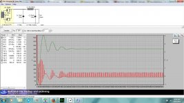
Add a resistor or choke after the cap and add another larger cap after the R or L. The ripple will smooth out considerably.
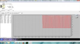
Ok will do. But am I reading the graph correctly, that there's over 4v of ripple left on the DC, or does it not work like that?
Ok will do. But am I reading the graph correctly, that there's over 4v of ripple left on the DC, or does it not work like that?
You're reading it right but the design is incomplete. You need the other components to provide the filtering you want. With a single cap and nothing else, you will have very high ripple. It's just a few clicks of the mouse so give it a try.
See the attachment for an example. This isn't optimum, just showing an example.
Attachments
Last edited:
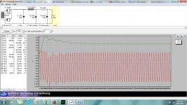
Ok, playing around with the PSUD a little more. For guitar amp applications, what is an acceptable amount of ripple... 1v? .5v? Less, more? Just trying to get an idea of what is reasonable.. One thing to note, I don't like my amps sounding too "tight".
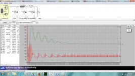
A second question, What are those wavey patterns that smooth out from left to right? They take up more of the graph in the second image with another filter added on. Is this a graph that accounts for time and that is what the forms look like when it's first switched on?
A second question, What are those wavey patterns that smooth out from left to right? They take up more of the graph in the second image with another filter added on. Is this a graph that accounts for time and that is what the forms look like when it's first switched on?
Attachments
Ok will do. But am I reading the graph correctly, that there's over 4v of ripple left on the DC, or does it not work like that?
You selected and were showing I for C1 which is CURRENT in Amperes.
Select V for C1 which is VOLTAGE in VAC !!
Have fun learning. PSUD is cool.
Jeff
Add a current tap in parallel with C2. That will represent the load established by your output tubes so use an appropriate current, say 100mA. R2 represents the driver stage and can be a current tap also instead of the resistor. You will then look at the voltage waveforms on C2 and C3 which are in parallel with the loads.
- Status
- This old topic is closed. If you want to reopen this topic, contact a moderator using the "Report Post" button.
- Home
- Amplifiers
- Tubes / Valves
- Rectifier and DC filtering relationship question