One viewpoint is not about protecting the valve diode, but rather in protecting the PT and/or choke.
A valve diode may well be very reliable, and be of an improved type which has mitigated common failure modes - even the 6CJ3 datasheet indicates the device is aimed at reduced failure from anode-cathode arcing. But arcing can also occur at the valve socket or on the base due to pollution and the single-ended connections in that damper diode. PT primary or secondary CT fusing should alleviate gross PT stress once failure current level becomes substantial enough. But for some, a few cents of protection may provide an alternative form of cheap insurance.
A step fault current in the inductor circuit may well stress the choke and PT, and contribute to tracking across the diodes. Sure, a bad socket pin or broken wire or dud CT fuse may not cause a problem at the same time as high choke current conduction. But similar to some zero-cost diodes, a few mains MOVs are also pretty simple insurance. OT protection may be a much sexier topic than protecting chokes, but the gist is the same. Imho, I'm happy to use any modern part or practise or knowledge to make an old amp cope better and last longer.
Last edited:
I did a PP once that used 6550s at one point, and while I can't remember some of the details I recall that using a mercury rectifier made an improvement. This of course isn't a suggestion that mercury is good, but it could be worthwhile watching your series resistance with a PP amp.What about tube rectification? I'm not a fan, but that should slow the spikes, etc.
This is for a PP 6550 amp. Would a GZ34 or 5AR4 be a better choice?
At the voltage levels in this supply I don't see a problem, provided the amp is regularly maintained (i.e. sockets blown clean, etc). At much higher voltages, I would prefer a damper diode with a top cap for the cathode connection. This is probably the most common configuration for higher powered damper diodes. The heater pins are still at the base, well separated from the plate pin. Here, the heater can either be floated or connected to the cathode through a large value resistor. The latter is a better idea, since it avoids potential buildup between heater and cathode if a leakage path occurs between the anode and heater. Such a buildup could cause the heater insulation to fail, which would be A Bad Thing™.One viewpoint is not about protecting the valve diode, but rather in protecting the PT and/or choke.
A valve diode may well be very reliable, and be of an improved type which has mitigated common failure modes - even the 6CJ3 datasheet indicates the device is aimed at reduced failure from anode-cathode arcing. But arcing can also occur at the valve socket or on the base due to pollution and the single-ended connections in that damper diode.
Again, with the behavior of the choke input supply I find such measures unnecessary. If you feel the silicon diodes are more reliable than the tube rectifier, then why use the tube(s)? Similarly, I have found no conditions that would damage the choke. A 660V MOV across the choke will conduct every time the HV is switched on (when the capacitors are at 0V), due to the 850V potential difference across the choke at that time. This will eventually degrade and destroy the MOV. A better transient suppressor is a series RC, which can be placed across the choke, across the rectifiers, or from the choke-rectifier junction to ground.PT primary or secondary CT fusing should alleviate gross PT stress once failure current level becomes substantial enough. But for some, a few cents of protection may provide an alternative form of cheap insurance.
A step fault current in the inductor circuit may well stress the choke and PT, and contribute to tracking across the diodes. Sure, a bad socket pin or broken wire or dud CT fuse may not cause a problem at the same time as high choke current conduction. But similar to some zero-cost diodes, a few mains MOVs are also pretty simple insurance. OT protection may be a much sexier topic than protecting chokes, but the gist is the same. Imho, I'm happy to use any modern part or practise or knowledge to make an old amp cope better and last longer.
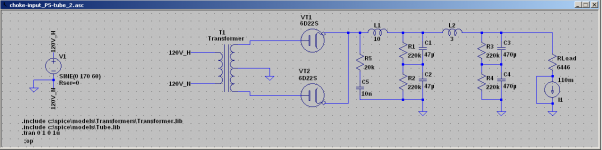
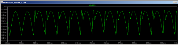
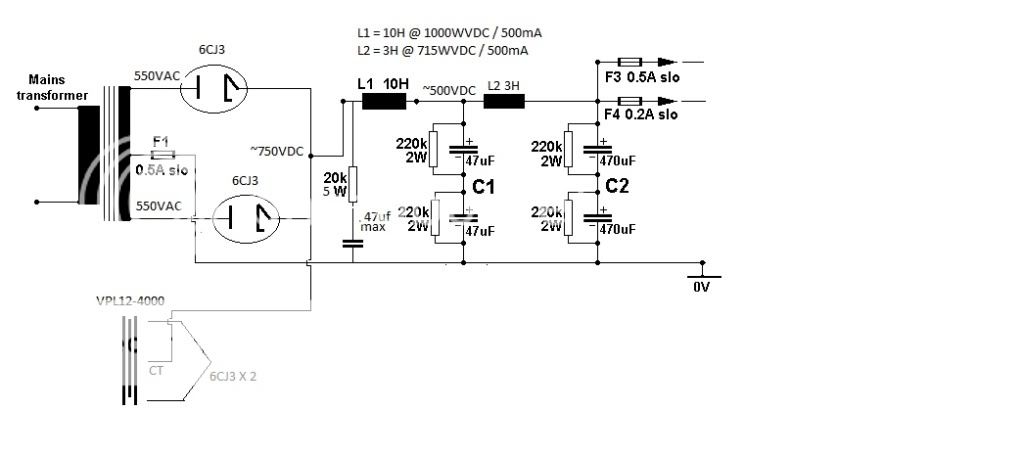
The variable we don't know is the parallel capacitance across the choke. This capacitance actually damps ringing. If the choke has a very low parallel C, it can ring at high frequency when the load current is below critical. A snubber of, say, 10nf in series with a 20k 5 watt resistor, would keep any transient peaks at bay. A revised schematic is in the first image. The second image shows the transient. In this particular waveform I reduced the parallel C of L1 to nil, and dropped the external load to nil as well. The parasitic spikes were 1.3+KV and several KHz without the snubber. As you can see, with the snubber the transient is a much lower frequency and effectively limited to the peak AC voltage. The cost is a few cents worth of parts and about 1.5 watts of heat in the resistor. As you say, cheap protection
")
Attachments
At the voltage levels in this supply I don't see a problem,
The concern is not so much the normal working voltages, but the fault condition voltages. If the supply to the choke was instantly interrupted for some reason (fuse?) the voltage across the inductor could skyrocket, leading to arcing across pins. Admiddedly you have some damping around the choke, but you never know.
The concern is not so much the normal working voltages, but the fault condition voltages. If the supply to the choke was instantly interrupted for some reason (fuse?) the voltage across the inductor could skyrocket, leading to arcing across pins. Admiddedly you have some damping around the choke, but you never know.
This greatly depends on where the circuit opens. If the connection between the choke and filter cap opens, then a very high voltage ringing waveform will be generated (were talking 10KV). Likewise, if the connection between the choke and rectifiers is broken OR center tap and ground is broken, you will get the very high voltage ringing. The former would require a broken connection between the choke and caps. The latter would mean a broken connection, simultaneous opening of both rectifiers, or a fuse in the center tap (which is a VERY BAD IDEA, for several reasons). A snubber on the input side of the choke will damp the HV oscillations, limiting them to about 1KV or so.
Fuses on the primary side of the trans are better. If the fuse blows here the input of the choke still has a path to ground through the capacitance of the rectifiers and trans secondary, which limits the resulting oscillation to about 1KV. If a snubber is used the oscillation is immediately damped.
That's one of the application advantages of a MOV across the choke winding - it loops the inductor current locally and should not itself be disconnected with the fault cause, and can be designed to cover the likely inductive joule capability, and quite rightly the peak working voltage (peak start-up applied voltage with some mains tolerance margin). I personally like MOVs because I have a good selection of them, but I also like their simplicity and somewhat soft clamping nature.
A broken connection in a non-conducting diode would not instigate an inductive spike problem, but I guess some forms of open-circuit failure, say from a valve socket pin or poor solder joint, may not behave like a simple one-way switch.
For a secondary side fault, a fuse placed on the secondary will have a somewhat better discrimination than a fuse placed on the primary. A secondary side fuse doesn't need to handle the primary turn-on current, which can often dictate using a higher current rating fuse than would be typically expected.
Last edited:
That's one of the application advantages of a MOV across the choke winding - it loops the inductor current locally and should not itself be disconnected with the fault cause, and can be designed to cover the likely inductive joule capability, and quite rightly the peak working voltage (peak start-up applied voltage with some mains tolerance margin). I personally like MOVs because I have a good selection of them, but I also like their simplicity and somewhat soft clamping nature.
MOV's are great for protection against random infrequent surges, but I would'nt use them to damp the surges that occur every time the supply is switched off. MOVs are known to degrade after handling repetitive surges. This is why I prefer RC snubbers.
It would have to affect both rectifiers simultaneously - a very unlikely event. Proper solder joints and quality sockets also mitigate such an event.A broken connection in a non-conducting diode would not instigate an inductive spike problem, but I guess some forms of open-circuit failure, say from a valve socket pin or poor solder joint, may not behave like a simple one-way switch.
True. However, we must closely examine the fusing arrangement. A secondary fuse provides no protection against shorts in the transformer or in any heater circuits that the transformer supplies. Furthermore, a single fuse in the CT offers no protection in the case of an (admittedly unlikely) short in both rectifiers, which is why I think it is a bad idea. The best bet for secondary fusing would be a fuse in each leg of the secondary between the trans and rectifier. Even so, primary fusing is still needed.For a secondary side fault, a fuse placed on the secondary will have a somewhat better discrimination than a fuse placed on the primary. A secondary side fuse doesn't need to handle the primary turn-on current, which can often dictate using a higher current rating fuse than would be typically expected.
The final issue relates to fuse specifications: I have seen a LOT of equipment with standard 250V fuses in the CT lead. The builders mistakenly believe that since the CT is at ground potential a LV fuse will work fine. They don't realize that when the fuse blows the voltage across the fuse will be equal to 1/2 secondary RMS voltage.
Turning off an amp at the primary winding would only cause the choke to stop conducting at the operating peak current point in the rectified waveform for a small percentage of instances. That operating current condition could vary from say idle operation, up to a cranked level, but I guess an idle condition is more likely. In comparison, a fault level of choke current would likely be significantly higher than a peak in the rectified current waveform for a cranked load, which would in turn be higher than an idle peak level - so for most turn-off instances, the choke current would be significantly lower than a fault level.
If one of the diodes is conducting at the turn-off instant, then the choke has a current conduction path through the PT secondary to initially dissipate some energy in to.
A MOV should be selected for some margin on the prospective fault peak (eg. limited just by known effective resistances), and the joule calculation would likely use the rated inductance, even though the inductance may be significantly lower at a fault current level. Turn-off events are not normally repetitive, so even a worst-case dump of inductor energy at an idle condition is likely to be a much lower joule level than the MOV is designed to withstand. Unfortunately assessing prospective fault current levels, and hence MOV joule rating is not a simple task.
A broken connection associated with one conducting diode would cause a choke inductive spike.
A short across both diodes would short the total secondary HT winding, in which case the primary side fuse should provide reasonable protection.
I think most builders are aware that a fuse in the secondary HT CT or in the legs of the HT are disconnecting the HT ACV. It is very rare that anyone would try and source a higher ACV rated fuse than 250V for the secondary HT for typical amps. Old amps have room for 3AG fuses, which is what I use. The fuse still operates, but like applying such a fuse in the B+ DC line, the fuse may end up damaged, cracked or splattered. Some heatshrink over the fuse can help constrain the debris - similar to applying heatshrink over a NTC or MOV. I've even seen a 1kV cap become a carbonised mess over a large area of pcb.
Last edited:
Both damper cathodes and both damper heaters should be at the same potential. Then, no issue of heater to cathode potential limit can surface.
Protection against inductive kick back spikes is needed, when SS diodes are mixed with choke I/P filtration. I don't see "sand" in this B+ PSU.
The voltage equalizing resistors shown will slowly bleed the filter caps. down.
If the B+ supply is charged up, so is the bias supply. Negative voltage on the O/P tubes' control grids provides electrostatic protection against cathode stripping.
Speaking of the bias supply, mention was made of having both a "free" 5 VAC winding and a free 6.3 VAC winding. Phase those windings up and wire them in series. Fewer stages of voltage multiplication will be needed, to obtain a satisfactory bias supply.
If a "fudge factor" cap. proves necessary, make sure you use a part rated for several thousand WVDC. The 0.47 μF. limit for the "fudge factor" part is to ensure that a cap. I/P filtered regime is not entered.

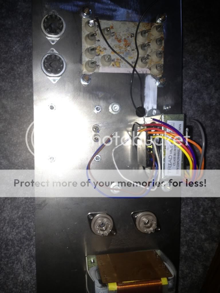
I ordered a few 6CJ3s and the triads. I just have to figure out how and where to mount the triads.
How much capacitance is going to be necessary for B+ filtration? Or, rather, how much can the 6CJ3s handle?
At the voltage levels in this supply I don't see a problem, provided the amp is regularly maintained (i.e. sockets blown clean, etc). At much higher voltages, I would prefer a damper diode with a top cap for the cathode connection. This is probably the most common configuration for higher powered damper diodes. The heater pins are still at the base, well separated from the plate pin. Here, the heater can either be floated or connected to the cathode through a large value resistor. The latter is a better idea, since it avoids potential buildup between heater and cathode if a leakage path occurs between the anode and heater. Such a buildup could cause the heater insulation to fail, which would be A Bad Thing™.
Again, with the behavior of the choke input supply I find such measures unnecessary. If you feel the silicon diodes are more reliable than the tube rectifier, then why use the tube(s)? Similarly, I have found no conditions that would damage the choke. A 660V MOV across the choke will conduct every time the HV is switched on (when the capacitors are at 0V), due to the 850V potential difference across the choke at that time. This will eventually degrade and destroy the MOV. A better transient suppressor is a series RC, which can be placed across the choke, across the rectifiers, or from the choke-rectifier junction to ground.
The variable we don't know is the parallel capacitance across the choke. This capacitance actually damps ringing. If the choke has a very low parallel C, it can ring at high frequency when the load current is below critical. A snubber of, say, 10nf in series with a 20k 5 watt resistor, would keep any transient peaks at bay. A revised schematic is in the first image. The second image shows the transient. In this particular waveform I reduced the parallel C of L1 to nil, and dropped the external load to nil as well. The parasitic spikes were 1.3+KV and several KHz without the snubber. As you can see, with the snubber the transient is a much lower frequency and effectively limited to the peak AC voltage. The cost is a few cents worth of parts and about 1.5 watts of heat in the resistor. As you say, cheap protection
Thanks for taking the time to draw that schematic! What wattage are the sharing resistors across the caps? Can I safely use 500V caps in this supply? Would a thermistor slow the voltage spikes at startup if placed on the primary of the big power transformer?
Thanks again!
Blair
Thanks for taking the time to draw that schematic! What wattage are the sharing resistors across the caps?
I will spare you the math and give you the answer: 2 watts minimum. That provides a very comfortable safety margin. The resistors also need to withstand the highest possible voltage (425V in this case).
Can I safely use 500V caps in this supply?
If you run two in series, then yes. Otherwise, no. The total voltage rating needs to be 850V minimum, but if I am running 2 in series I would go with 1kv total for a safety margin.
Would a thermistor slow the voltage spikes at startup if placed on the primary of the big power transformer?
Voltage spikes are only a real problem during certain fault conditions. Run the snubber I showed in the schematic and you will be fine.
I use the BCcomponents PRO2 range, which is a suitably small 'old looking' 2W resistor with a 500V DC or RMS continuous rating to some IEC standard. That gets me through normal electrolytic capacitor bleed applications. For personal use, I'm happy to put that resistor in somewhat higher continuous conditions, although that's pretty rare even in larger power amplifier applications.
used in ef86 circuit a 0,6W 470k carbon (not exceeding power rating, but voltage rating a bit) after few minutes it became several megohmsWow. I've never even looked! What happens if they are underrated? Do they break down, arc, or something worse?
no magic dust or sparks released..
Hello Eli, or anyone else that knows
I have the VPL12-4000. The schematic shows two sets of 6.3V windings. Easy enough to understand. Both sets of windings have center taps. Do I need to ground the center taps? Is the center tap where the cathodes of the 6CJ3 ties in?
Never mind. I see that grounding the center tap would be a direct short. Dumb, pre-coffee question.
Still, my question is, "Does the center tap connect to the cathodes?"
Thank you!
Thank you!
Blair
Last edited:
- Status
- This old topic is closed. If you want to reopen this topic, contact a moderator using the "Report Post" button.
- Home
- Amplifiers
- Tubes / Valves
- Choke ratings and resistor values in choke input supply?