http://www.turneraudio.com.au/audiofilt ... page2.html
I am looking at this PS site from Patrick Turner (the traditional choke input), and noticed that the 6K bleeders are 30W! Do these really have to be 30W?
The other question is that the second choke (L2 in the image) I have is only rated at 715 WVDC. My supply transformer is 1100VCT. Would a current limiter help the startup spikes? Is it OK to use the 715V choke in the second position?
Thanks!
Blair
He is using the resistors to load the transformer and thus lower the output voltage.
Another way to accomplish this might be to add a capacitor at the output of the rectifiers and input of the first inductor. This would be a cap input filter, although the first cap would be small (probably 1-10uF). The larger the cap the lower the voltage out.
Another way to accomplish this might be to add a capacitor at the output of the rectifiers and input of the first inductor. This would be a cap input filter, although the first cap would be small (probably 1-10uF). The larger the cap the lower the voltage out.
It looked kind of strange.
He is using a higher voltage transformer than I have. Mine tests at 1200vct unloaded, so I assume it will drop quite a bit under load.
I do not mind using his schematic. I found some 6K ceramics that are 25W on eBay. It just seemed like a hefty W rating and load on the transformer.
He is using a higher voltage transformer than I have. Mine tests at 1200vct unloaded, so I assume it will drop quite a bit under load.
I do not mind using his schematic. I found some 6K ceramics that are 25W on eBay. It just seemed like a hefty W rating and load on the transformer.
Other way round.TheGimp said:The larger the cap the lower the voltage out.
One way to limit the off-load voltage of a choke input supply is to use a string of high power zeners. If their combined voltage is a bit higher than the on-load voltage then they don't waste any power under normal conditions. You still need a small bleeder too.
Putting chokes in the negative side is a standard technique for avoiding high DC voltages on the choke. For the first choke in a choke input supply this gains you less, as it still has a high AC voltage to cope with.
Putting the choke on the center tap also puts a bias on your power transformer. I was taught to never put anything on the centertap and maybe this is why. I didn't know or consider that doing so lowers the dc on the choke there. Could be handy. I think if your chokes are rated for your draw at that voltage then keep them off the center tap. If you still have hash on your line after your supply is built then that small value high voltage cap after the rectifier is the only cure i've found. On lower voltage supplies i've never needed it.
There's also a range of current draw that gives the best regulation and the bleeder can be adjusted to arrive at this. I have to remember where I read thisthough. The math didn't look to bad if i remember correctly.
There's also a range of current draw that gives the best regulation and the bleeder can be adjusted to arrive at this. I have to remember where I read thisthough. The math didn't look to bad if i remember correctly.
Pretty tall order for a tube rectifier. I'm getting by with a 5U4GB at 500 volts and I'm sure it's just sqeeking by. All the charts really narrow down with higher current draw and voltage with choke input. The only thing i like about the tube rectification with it is that the rectifier being on the edge will blow probably sooner than ss diodes that might keep delivering should something go wrong. Like an expensive fuse. The higher the voltage the scarrier it gets. 500 volts is my limit.
I don't know how it would behave with a push pull. All I can say is try it and see. What i can say for sure is you'll see less voltage drop the more class a push pull you run.
I don't know how it would behave with a push pull. All I can say is try it and see. What i can say for sure is you'll see less voltage drop the more class a push pull you run.
You are probably right to stick with SS rectification.
Someone has also suggested a fly back diode as well as snubber caps across the first inductor to help with peaks.
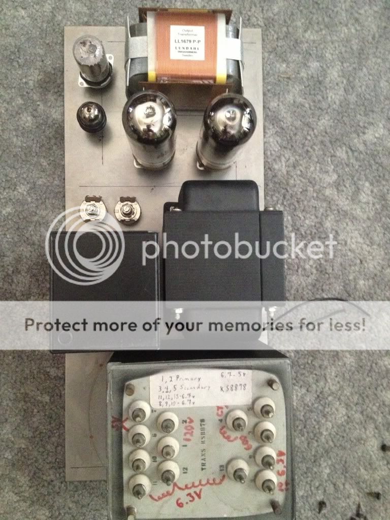
I think this is the layout I'm going with. I will cut the plates today so I am committed") or, this could go on forever.
or, this could go on forever.
Someone has also suggested a fly back diode as well as snubber caps across the first inductor to help with peaks.
I think this is the layout I'm going with. I will cut the plates today so I am committed
or, this could go on forever.
I'd say definitely breadboard it before committing any materials. From what I've seen on the supplies I've made is that it prob won't give the regulation you want even with SS rect. I believe the trick for regulation is using a swing choke choke and adjusting many more factors for a range of current draw. No small task.
Sorry. This is occurring to me slowly since I just like playing with and maybe even more talking about choke IF power supplies. Seems to me like a cap input supply with active shunt regulation would serve you better and be less hot, heavy, and scary and prob actually work well.
I've got to scoot. I just had to say something. That's some pretty stuff you have there and it would be awesome if it worked well too. You'd have to get advice from someone other than me for a shunt regulator though. Definitely get a second or third opinion. -Fred
Sorry. This is occurring to me slowly since I just like playing with and maybe even more talking about choke IF power supplies
. Seems to me like a cap input supply with active shunt regulation would serve you better and be less hot, heavy, and scary and prob actually work well.I've got to scoot. I just had to say something. That's some pretty stuff you have there and it would be awesome if it worked well too. You'd have to get advice from someone other than me for a shunt regulator though. Definitely get a second or third opinion. -Fred
- Status
- This old topic is closed. If you want to reopen this topic, contact a moderator using the "Report Post" button.
- Home
- Amplifiers
- Tubes / Valves
- Choke ratings and resistor values in choke input supply?