Hello
I need litle help, i am looking for schematic of good driver stage for cathode follower output stage, driver stage must have amplification of 250,300 times..i have tube 6sl7 it will be good some project with that tube but it is not so important
Thank you, best regards!
I need litle help, i am looking for schematic of good driver stage for cathode follower output stage, driver stage must have amplification of 250,300 times..i have tube 6sl7 it will be good some project with that tube but it is not so important
Thank you, best regards!
Have a look at the Impasse Pre-amplifier thread.
Although its quite long the schematic appears towards the end of the thread.
http://www.diyaudio.com/forums/pass-labs/136835-impasse-preamplifier.html
Although its quite long the schematic appears towards the end of the thread.
http://www.diyaudio.com/forums/pass-labs/136835-impasse-preamplifier.html
Hello
I need litle help, i am looking for schematic of good driver stage for cathode follower output stage, driver stage must have amplification of 250,300 times..i have tube 6sl7 it will be good some project with that tube but it is not so important
Thank you, best regards!
More than 106dB?? Open loop or closed loop?
jan
Hello
I need litle help, i am looking for schematic of good driver stage for cathode follower output stage, driver stage must have amplification of 250,300 times..i have tube 6sl7 it will be good some project with that tube but it is not so important
CF output stages are problematic, not just because of the huge swings required (many hundreds of volts), but handling the heater-cathode interface. They can be done, but in practice the tradeoffs (notably higher driver stage distortion) make the exercise futile. You need not just gain, but large signal capability. This means lots of high voltages and driver tubes that can take it.
There's an excellent walk-though of CF amplifier design in Crowhurst's "Understanding Hifi Circuits." He ends up showing that you're best off bootstrapping the driver, which adds distortion that the CF output stage originally reduced. No free lunch.
300x is 20log300=~50dB !jan.didden said:More than 106dB?? Open loop or closed loop?
106dB gives ¨10^(106/20) ,is over 100k X.
Mona
There's an excellent walk-though of CF amplifier design in Crowhurst's "Understanding Hifi Circuits." He ends up showing that you're best off bootstrapping the driver, which adds distortion that the CF output stage originally reduced. No free lunch.
McIntosh used bootstrapping (positive feedback) in their unity coupled O/P stages, for exactly the reason SY stated.
A COSTLY method that might work is to use step up transformer coupling at the O/P stage's I/P. If nothing else, cathode followers present a very light load to the driving circuitry. TANSTAAFL rules again. In addition to the expensive interstage "iron", absolutely top notch O/P transformers are needed too. $$$
 Don't even think about an interstage trafo inside a NFB loop! That means the O/P trafo get's no help from NFB.
http://www.tubecad.com/2005/July/07/Bootstrapping.png
do you mean this can be work? just one more stage before
do you mean this can be work? just one more stage before
But that's no PREamp !http://www.tubecad.com/2005/July/07/Bootstrapping.png
do you mean this can be work? just one more stage before
To better suggest a possible solution some questions.
What are the max.signal levels
Witch supply voltages do you have
Do you have a tube in mind for the cathode-follower
Or maybe a emitter follower
Any frequency correction
Input impedance
Mona
yes problem is punctuation...it is 250 or 300
Please tell us the maximum input voltage to this stage (include normal and expected overloads) and we will offer you some solutions.
Thank you very much..OK i want to build this amp SETA - Single Ended Tube Amplifier
but without interstage trafo...i see some solution here..but also with trafo or choke
cathode-follower output stage design part-3
but without interstage trafo...i see some solution here..but also with trafo or choke
cathode-follower output stage design part-3
The transformer is key- it doubles the available voltage swing at the driver. You can't get rid of it without a complete redesign with very high voltages and the tubes that can take it and remain reasonably linear. I would not recommend this- it will be expensive, dangerous, and prone to failure unless designed and built by an expert. And even then, it is likely to be less linear.
There are some other fundamental problems with this circuit, notably the complete neglect of heater-cathode issues.
If your heart is set on a cathode follower amp, you'd do better with something like a paralleled 6528 driving a 1k primary and perhaps 375 volts on the plate (I haven't done the loadlines, so this is a WAG). It will still take a pile of drive voltage, but the heater-cathode issues go away and the damping factor is likely to be higher.
http://www.tubecad.com/2005/July/07/ChokeLoad.png
Ok , i understand, thank you-do you think that this schematic it will be good ...just i am not shure for 100H choke...is it too low for 20Hz..
Ok , i understand, thank you-do you think that this schematic it will be good ...just i am not shure for 100H choke...is it too low for 20Hz..
Thank you very much..OK i want to build this amp SETA - Single Ended Tube Amplifier
but without interstage trafo.....<snip>
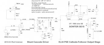
The output stage of that design is not optimal. The price of KT88s is double the price of EL34s, and KT90/120 are even less favourable. Meanwhile EL34 PSE can perform very well at low B+ - like 300V. With 2 in parallel, the slope is 22mA/V, assuring us a very low driving impedance. With the 75 ohm dc of the SE15 OT primary, we only need 43 ohm to self-bias the EL34s - meaning no need for ugly-sounding cathode bypass electrolytic capacitor!
We cannot skimp on the OT, as Eli noted. I like the Sowter SE15 (1500 ohm, 180mA, 14H) in this position, and recommend them for high quality and reliability, and reassurance of 2500V flash test.
For the driver, we have yet another situation where Shunt Cascode can save us from bad-sounding multiple stages of medium-mu. Unlike ordinary triode stages, we can refer the output to a negative voltage - meaning that no excessive supply voltages are needed.
The picture shows a completed serving suggestion: With the SE15 OT it can do about 9W rms clean, and moderate levels of listening model < 0.1% distortion. So the circuit can be run open-loop with confidence of good sound.
The whole circuit can be dc-coupled, on account of the negative driver supply. In this case, the dc-offset null servo that I showed in the "All DHT Headphone amp" thread can be adapted.
The drawback for some DIYers: this circuit can't really be made point-to-point. A PCB is needed to get the loop areas (EM-moment) small enough, and to accommodate SMD chip-ferrites in many positions of this very-high gain driver. And SMD parts generally, like the superb new 500V PNP PBHV9040Z from NXP semiconductors.
I have some PCBs here, and will get around to fully characterising them at some point.
Attachments
Another way to get high gain and good drive capabilities in a single stage is to try a resistively loaded pentode with a CCS assist. You can use a high value resistor to get the gain up, the CCS provides additional current to get the pentode into a good operating point, and you can use the MU output of the CCS to drive the next stage.
Using 1/2 of a 6BN11 pentode with CCS the circuit had a gain of 192 and output impedance of 500 ohms. Distortion was .54% at 90Vrms.
I'm sure that with some of the other high transconductance pentodes the gain could be pushed higher.
Look at the Pentode + CCS driver page under Driver Experiments on my web page for more details.
- Status
- This old topic is closed. If you want to reopen this topic, contact a moderator using the "Report Post" button.
- Home
- Amplifiers
- Tubes / Valves
- preamplifier with huge amplification