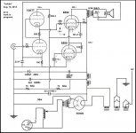
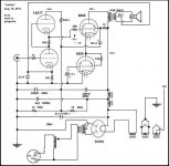
Hi. This is my current project. I have a fascination with direct connected amps and single drivers so I keep trying. In fact it's inspiring me to learn electronic theory. Every time I learn something and apply it I'm rewarded with better sound.
The small bypass capacitor on the cathode resistor on V1 picks up the dip in the freq response left by the feedback scheme and the high output impedance. The output droops after 30K and there's a "bump" at the low end which I'm not used to but I like the sound of it. Surprising amount of bass.
There is some rounding of the bottom of the sine wave around 2k and then some rounding at the top of the wave around 20k (or is it too pointy on the other side?). I'm hoping to correct this but I like the sound of the system. But still...
Without the feedback scheme the wave is better shaped throughout but the output follows the impedance of the speaker. Also without the feedback scheme and cathode bypass is sounds very "tizzy". Definitely better with it.
The circuit with the stacked 6550's is something I dreamed up one morning and thought it could never work but then I tried it one evening and within a couple of hours it was passing signal to my surprise.
I'm hoping that balancing the output to the speaker and tapping that for use of the cathode resistor as a feedback sense resistor is canceling the back emf from the speaker and not introducing the back emf into the amplifier. Sorry, that was a terrible sentence.
The speaker is my usual 1/4 tuned transmission line stuffed with shredded denim with a 5" full range Dayton driver and a top mounted reflector.
sweep from 20 to 40k:
Direct Connected 12AT7/6550 to Single Driver/Speaker - swqeep 20 to 40kHz - YouTube
20k square wave:
Direct Connected 12AT7/6550 to Single Driver/Speaker - 2k square wave - YouTube
I increased the volume to full output but started it out lower just to be more gentle on things.
playing some music:
Direct Connected 12AT7/6550 to Single Driver/Speaker - playing some music - YouTube
Thanks for looking and letting me post my project. I can only tell my friends about this stuff so much before they fall asleep. I play in a band so I have lots of stories to tell thankfully. -Fred
Attachments
Hi. This is my current project. I have a fascination with direct connected amps and single drivers so I keep trying. In fact it's inspiring me to learn electronic theory. Every time I learn something and apply it I'm rewarded with better sound.
The small bypass capacitor on the cathode resistor on V1 picks up the dip in the freq response left by the feedback scheme and the high output impedance. The output droops after 30K and there's a "bump" at the low end which I'm not used to but I like the sound of it. Surprising amount of bass.
There is some rounding of the bottom of the sine wave around 2k and then some rounding at the top of the wave around 20k (or is it too pointy on the other side?). I'm hoping to correct this but I like the sound of the system. But still...
Without the feedback scheme the wave is better shaped throughout but the output follows the impedance of the speaker. Also without the feedback scheme and cathode bypass is sounds very "tizzy". Definitely better with it.
The circuit with the stacked 6550's is something I dreamed up one morning and thought it could never work but then I tried it one evening and within a couple of hours it was passing signal to my surprise.
I'm hoping that balancing the output to the speaker and tapping that for use of the cathode resistor as a feedback sense resistor is canceling the back emf from the speaker and not introducing the back emf into the amplifier. Sorry, that was a terrible sentence.
The speaker is my usual 1/4 tuned transmission line stuffed with shredded denim with a 5" full range Dayton driver and a top mounted reflector.
sweep from 20 to 40k:
Direct Connected 12AT7/6550 to Single Driver/Speaker - swqeep 20 to 40kHz - YouTube
20k square wave:
Direct Connected 12AT7/6550 to Single Driver/Speaker - 2k square wave - YouTube
I increased the volume to full output but started it out lower just to be more gentle on things.
playing some music:
Direct Connected 12AT7/6550 to Single Driver/Speaker - playing some music - YouTube
Thanks for looking and letting me post my project. I can only tell my friends about this stuff so much before they fall asleep. I play in a band so I have lots of stories to tell thankfully. -Fred
The feedback looks odd; do you have a typo in your schematic? The OT secondary is seemingly floating, other than the single connection from the centre tap to the 12AT7 cathode.
Chris
Why two power tubes in series, the lower doing nothing more that waste power? As CCS, the cathode is at high AC potential, so av aprox. 1 in all the stage?
Also add equalizer resistors across electrolytic capacitors.
With little effort you can rewire the output stage to a WCF, and a lower turns ratio transformer can be used.
Also add equalizer resistors across electrolytic capacitors.
With little effort you can rewire the output stage to a WCF, and a lower turns ratio transformer can be used.
Last edited:
As Chris mentioned, there are issues with the feedback circuit:
You need to ground one terminal or there is no current path and no voltage reverence point for feedback.
Since you show an 8R speaker, I would suggest connecting it to the 8R tap rather than the 16R tap, and connect the bottom connection to ground and use the top 16R tap for feedback.
Place a resistor between the feedback tap of the transformer and the cathode of the bottom 12AX7. Remove the bypass capacitor from the cathode.
You can then adjust the ratio of the feedback resistor to the cathode resistor to adjust your level of feedback.
Remove the bypass capacitor from the cathode.
A .22µF in // with 100 ohms isn't a true bypass...
Hi. Thank you all so much for taking a look. I'm still absorbing a lot of the information.
I believe it is floating. I didn't really know how to feel about it. I just thought I'd try it but your post made me see it in a different way and I now believe it is floating.
Indeed, it is. I turn off the bench lights when I'm listening to it as an attempt to justify it. Turns out to be about the same draw as three CFL's @ 20 watts draw and an LED bulb at about 10. I'm normally pretty energy conscious until it comes to tubes and music.
I'll have to say yes because I'm not too shabby at putting things together from a schematic. And it has been completely apart and put back together twice with other operating circuits put together in between. I know it's unusual, not for me anyway, but it is a very simple circuit and not difficult to make on the bench.
I did, however, swap the two 6550's and there was a change of bias and current draw, so it's a bit touchy, but it works.
I'm very interested in this. I'm very inspired to give it a try. Thank you for suggesting it and bringing it to my attention.
When I have the funds, I will be shopping for a lower turns ratio transformer. In the meantime I'll experiment with White cathode followers so I hopefully have an idea of which turns ratio/ballpark impedance transformer to get.
Thank you for the feedback scheme you describe. I always like the idea of using the various taps for different things. I want to give your suggestion a shot when I get a lower turns ratio transformer with the CWF on the 2nd stage.
As a point of possible interest, though, there appears to be some sort of feedback taking place as is. The effect of the 8 ohm tap to the cathode of the 12AT7, in this configuration, is not subtle. The bass is boosted quite a bit and the high frequencies are lowered quite a bit.
Perhaps it is a false bypass.
Everybody's comments have helped me much and will continue to as it sinks in more. Thank you very much. -Fred
The OT secondary is seemingly floating, other than the single connection from the centre tap to the 12AT7 cathode.
I believe it is floating. I didn't really know how to feel about it. I just thought I'd try it but your post made me see it in a different way and I now believe it is floating.
Looks massively inefficient.
Indeed, it is. I turn off the bench lights when I'm listening to it as an attempt to justify it. Turns out to be about the same draw as three CFL's @ 20 watts draw and an LED bulb at about 10. I'm normally pretty energy conscious until it comes to tubes and music.
Are you sure that is really the circuit you are listening to?
I'll have to say yes because I'm not too shabby at putting things together from a schematic. And it has been completely apart and put back together twice with other operating circuits put together in between. I know it's unusual, not for me anyway, but it is a very simple circuit and not difficult to make on the bench.
I did, however, swap the two 6550's and there was a change of bias and current draw, so it's a bit touchy, but it works.
With little effort you can rewire the output stage to a WCF, and a lower turns ratio transformer can be used.
I'm very interested in this. I'm very inspired to give it a try. Thank you for suggesting it and bringing it to my attention.
When I have the funds, I will be shopping for a lower turns ratio transformer. In the meantime I'll experiment with White cathode followers so I hopefully have an idea of which turns ratio/ballpark impedance transformer to get.
You need to ground one terminal or there is no current path and no voltage reverence point for feedback
Thank you for the feedback scheme you describe. I always like the idea of using the various taps for different things. I want to give your suggestion a shot when I get a lower turns ratio transformer with the CWF on the 2nd stage.
As a point of possible interest, though, there appears to be some sort of feedback taking place as is. The effect of the 8 ohm tap to the cathode of the 12AT7, in this configuration, is not subtle. The bass is boosted quite a bit and the high frequencies are lowered quite a bit.
A .22µF in // with 100 ohms isn't a true bypass
Perhaps it is a false bypass.
Everybody's comments have helped me much and will continue to as it sinks in more. Thank you very much. -Fred
I believe it is floating. I didn't really know how to feel about it. I just thought I'd try it but your post made me see it in a different way and I now believe it is floating.
If the secondary winding is floating, the feedback won't work.
I would strongly encourage the person who drew the schematic to use solder dots rather than hoopti-hoops to indicate whether two wires are connected.
~Tom
As a point of possible interest, though, there appears to be some sort of feedback taking place as is. The effect of the 8 ohm tap to the cathode of the 12AT7, in this configuration, is not subtle. The bass is boosted quite a bit and the high frequencies are lowered quite a bit.
Assuming the schematic you posted is correct, any feedback effect you are getting at the moment must be depending on the capacitive coupling between the primary and secondary windings of the output transformer, I suppose. It seems hard to imagine that that could have any significant effect, especially on the bass, since it is feeding back into 100 ohms at the cathode.
If you have a meter, it would be interesting to know what resistance you measure between one of the loudspeaker terminals and ground. (Measured while amp is switched off, of course.) This could serve to confirm whether the OPT secondary really is otherwise floating, or not.
Chris
you can triode connect the 6550's,
do a Broskie Aikido configuration
Hi. I love reading Tubecad. That guy is a great writer.
If the secondary winding is floating, the feedback won't work.
I think I confused myself by trying to imagine what balancing action is taking taking place there. To look at the output, I have the scope on one lead to the speaker and the other on the common ground. The oscilloscope is closed when hooked up this way, so definitely not floating. Thank you.
I would strongly encourage the person who drew the schematic to use solder dots rather than hoopti-hoops to indicate whether two wires are connected.
I'll use dots and hoopties from now on.
any feedback effect you are getting at the moment must be depending on the capacitive coupling between the primary and secondary windings of the output transformer
The idea that this could be what is taking place is really exciting to me. I realize my designs need a feedback loop that includes the output transformer.
I hope to have the skills in the near future to compensate the phase of the feedback. I'm still pretty early on in my studies in this regard though.
it would be interesting to know what resistance you measure between one of the loudspeaker terminals and ground
I measured about 100 ohms between each speaker lead and ground on an old kludgy analog meter I got at goodwill.
I've got an old giant 50 watt 500 ohm rheostat as the 12AT7 cathode resistor. If I sweep it it's kind of like a mild tone/presence control. I have it set about 1/5th of the way so the meter is in the ballpark.
Thank you guys for talking with me about this thing. -Fred
Attachments
20k square wave:
Direct Connected 12AT7/6550 to Single Driver/Speaker - 2k square wave - YouTube
I increased the volume to full output but started it out lower just to be more gentle on things.
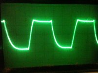
This is at 20Khz or 2Khz? Man, that lead edge of the square wave is brutal. I have found that any spike in the lead edge of a square wave, when I test my amps, means a harshness in the sound quality and for me, a lot of ear fatigue when listening to the amp. What does the square wave look like through a simple resistor load? I am assuming, from what you have written here, that the load is a speaker. Did you have any negative feedback enabled when you produced this wave from?
Direct Connected 12AT7/6550 to Single Driver/Speaker - 2k square wave - YouTube
I increased the volume to full output but started it out lower just to be more gentle on things.
This is at 20Khz or 2Khz? Man, that lead edge of the square wave is brutal. I have found that any spike in the lead edge of a square wave, when I test my amps, means a harshness in the sound quality and for me, a lot of ear fatigue when listening to the amp. What does the square wave look like through a simple resistor load? I am assuming, from what you have written here, that the load is a speaker. Did you have any negative feedback enabled when you produced this wave from?
This is at 20Khz or 2Khz?
Hell, I need an editor. I see my error. It's a 2kHz square wave.
I am assuming, from what you have written here, that the load is a speaker.
Yes, the load was the speaker on the video and everything was connected as it is on the schematic.
Without the feedback loop, the rise is higher on the square wave. Also with the speaker as the load.
BTW, this is the best square wave performance I've had out of any amp I've made so far. Earlier ones were totally crazy. I mean totally as in not safe.
What does the square wave look like through a simple resistor load?
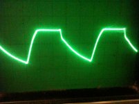
The results are attached below. I hooked up an 8 ohm 25 watt rheostat as the load. The shape didn't change much from low volume to max on my sound card. The first pic is without the bypass resistor and the 8 ohm tap run to ground. The second pic is what's on the schematic with the bypass resistor and 8 ohm tap running to the cathode of the 12AT7.
I remember seeing a square wave distortion guide with pictures and the likely distortion culprits and their deviations on the shape of the wave. I hope I can find it again.
I ran it at full volume for quite a bit and the rheostat was warm but not hot like I was expecting.
Thanks for taking a look and giving me a use for my morning coffee.
-Fred
Attachments
I measured about 100 ohms between each speaker lead and ground on an old kludgy analog meter I got at goodwill.
-Fred
So, your output is not grounded except for the feedback circuit. I think this is not what you want. Not an expert on these things, but I had odd warts and farts on my mark III build until I grounded the secondary of the opt. Ground the ground speaker tap. 100 ohms does not mean grounded. 0 ohms means grounded.
100 ohms does not mean grounded. 0 ohms means grounded.
I hadn't thought of that. I was merely concerned whether it was floating or not.
Here is an interesting and very informative thread related to grounding the output:
http://www.diyaudio.com/forums/tubelab/179992-tubelab-se-output-transformer-grounding.html
My plan isn't to build a stand alone amplifier but a powered speaker that is all contained but I'm still very glad to know this. Currently it's on the bench with a powder fire extinguisher nearby.
You've given me much food for thought. Thank you. -Fred
Hell, I need an editor. I see my error. It's a 2kHz square wave.
Yes, the load was the speaker on the video and everything was connected as it is on the schematic.
Without the feedback loop, the rise is higher on the square wave. Also with the speaker as the load.
BTW, this is the best square wave performance I've had out of any amp I've made so far. Earlier ones were totally crazy. I mean totally as in not safe.
The results are attached below. I hooked up an 8 ohm 25 watt rheostat as the load. The shape didn't change much from low volume to max on my sound card. The first pic is without the bypass resistor and the 8 ohm tap run to ground. The second pic is what's on the schematic with the bypass resistor and 8 ohm tap running to the cathode of the 12AT7.
I remember seeing a square wave distortion guide with pictures and the likely distortion culprits and their deviations on the shape of the wave. I hope I can find it again.
I ran it at full volume for quite a bit and the rheostat was warm but not hot like I was expecting.
Thanks for taking a look and giving me a use for my morning coffee.
-Fred
It's not entirely clear to me what your test setup is. If I am understanding you correctly, that second scope trace is obtained with the amplifier configured as in your schematic, with the OPT secondary supposedly "floating" aside from the connection to the lower cathode of the input stage? However, you then connect the output to an oscilloscope (or computer with sound card?) Does that mean you are now grounding one of the OPT secondary terminals through the grounding of the oscilloscope? In which case, you now have the OPT centre-tap connected to the lower cathode of the input stage and, and one or other of the endpoints of the OPT secondary connected to amplifier ground via the two mains cords of the amplifier and the oscilloscope.
So apparently the 100 ohm cathode resistor in your schematic is being bypassed by one half of the OPT secondary, when your oscilloscope is hooked up for the measurement. This would completely change the operating point of the tube. And it's not clear which end of the OPT secondary is the one you are grounding, so the feedback, such as it is, could be either positive or negative depending on which OPT lead you chose to connect to oscilloscope ground. Anyway, maybe this might go some way to explaining the rather bad traces you are getting.
(Actually, it's not clear from you schematic what measures, if any, you have taken to connect amplifier signal ground to mains ground. The above was written under the assumption that your amplifier signal ground is connected directly to mains ground. If not, then depending on how you have it configured, some of the above statements might need modification.)
Chris
is the main purpose of the CCS in this case to allow getting things biased so it can be direct coupled?
Yes, you hit the nail on the head. Also I wanted to see if there was any balancing action that could counteract drift in the circuit. Unfortunately it eats a bunch of current but then it sounds nice and that's why I'm building it. So, yes, I'm conflicted.
what is the dynamic Z of that CCS?
If that tube stays there much longer, I'll try to find out since I'm now curious.
capacitors have "seasoning flavors" plus comfortable operating points aren't a bad idea
I'm planning on trying a bypassed resistor in place of that tube. I've got to buy one though unfortunately. Hopefully tomorrow.
BTW, my transmission line has a Karlson cut on the end and my name's Fred too! -Fred
It's not entirely clear to me what your test setup is.
This is where things could get confusing. I'll do my best.
Does that mean you are now grounding one of the OPT secondary terminals through the grounding of the oscilloscope?
Nope. The ground of the scope is on the common ground and the test lead is on either of the speaker lead.
The only difference between the tests is that one was taken as the circuit is shown in the schematic.
The other test was without the feedback loop. Meaning the 8 ohm tap was connected to common ground along with the oscilloscope ground and then the test lead of the scope was on either speaker lead (as well as the "bypass" capacitor removed).
To be sure, at no time was the oscilloscope ground connected to either of the speaker leads. This would cause some some unwanted behavior for sure as you mention.
I hope I cleared things up O.K. I've never written a description of a circuit or anything electronic before posting here. It's quite challenging. -Fred
BTW, I don't believe the secondary of the output transformer is floating since there is a ground reference through the 8 ohm tap and 100 ohm resistor and I'm to the point of loop equations with two batteries.
")
- Status
- This old topic is closed. If you want to reopen this topic, contact a moderator using the "Report Post" button.
- Home
- Amplifiers
- Tubes / Valves
- Direct connected madness