Well, in the case with your "feedback" (your second trace, I think), you are looking at a voltage that is the sum of what is on the lower cathode of the input tube plus the contribution from half of the OPT secondary. Depending on which OPT lead you are connecting to the scope input, that is either the cathode voltage plus an in-phase signal from the OPT, or else the cathode voltage with an out-of-phase signal from the OPT. In either case, it's not what you need to be looking at.This is where things could get confusing. I'll do my best.
Nope. The ground of the scope is on the common ground and the test lead is on either of the speaker lead.
You should do away with the rather flakey "feedback" you are using, with the single connection from an otherwise-floating OPT secondary to the cathode, and instead ground one side of the OPT secondary and run feedback through a resistor to the input stage. (Experiment will be needed to determine which end of the output secondary to gorund, so as to get negative and not positive feedback.) And then put the scope onto the non-grounded ended of the OPT secondary.
The other test was without the feedback loop. Meaning the 8 ohm tap was connected to common ground along with the oscilloscope ground and then the test lead of the scope was on either speaker lead (as well as the "bypass" capacitor removed).
To be sure, at no time was the oscilloscope ground connected to either of the speaker leads. This would cause some some unwanted behavior for sure as you mention.
I hope I cleared things up O.K. I've never written a description of a circuit or anything electronic before posting here. It's quite challenging. -Fred
BTW, I don't believe the secondary of the output transformer is floating since there is a ground reference through the 8 ohm tap and 100 ohm resistor and I'm to the point of loop equations with two batteries.")
In this case (your first trace, and no feedback), you are indeed connecting the scope in the right way to see what is coming from the OPT secondary. But it would be better to ground one end of the OPT secondary rather than the centre-tap, and put the scope lead onto the other end. (So that you are looking at the full signal that goes to the speaker, rather than from grounded centre tap (not connected to either speaker wire) and a speaker wire.)
When I said the OPT secondary was "floating," I meant (and may indeed have said) "otherwise floating." That is to say, it would be floating aside from the single connection from the cnetre-tap to the input stage cathode. Which means there is no sensible and controlled feedback going on; just whatever might feed back via the capactiance between OPT primary and secondary.
Chris
Last edited:
When I said the OPT secondary was "floating," I meant (and may indeed have said) "otherwise floating."
Chris
I had a feeling that is what you meant. I just wanted to be sure.
instead ground one side of the OPT secondary and run feedback through a resistor to the input stage
I gave that a shot yesterday afternoon. I didn't like it so much although I know it's a proper technique and very good advice. I think it lowered the output impedance and that's not what I'm going for.
I want to try TheGimp's feedback he mentioned but I want a lower turns ratio output transformer so I can keep the output impedance high since I'm maxed out on the one I have.
I think the high output impedance is what I like about pentodes on the output stage but I find don't like ringing output transformers at all. I think my feedback scheme may be only quieting a bit of transformer ring and I find that really exciting.
This is excellent and just what I was hoping for posting here. Thank you. -Fred
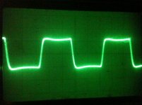
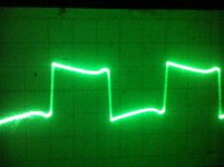
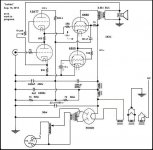
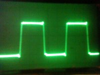
One more thing: I want to incorporate a lag and compensation scheme to a feedback loop of some sort so yesterday I applied a digital filter to a 2 kHz square wave. I did this to maybe help me comprehend what I'm up against. Below are to two traces of square waves with a 20 db cut centered at 39K.
This requires the audio to be at 96k sample rate and I'm sure would be better if it were higher but that is the max of my soundcard. The 1 kHz trace I did this morning because I wanted to see what change it would have. Looks like it has helped the overshoot on the leading edge anyway.
On both traces the speaker is the load. The first one is 2 kHz and the second is 1 kHz.
I played some 96k music files through the same filter and it sounded great.
I'll be moving this project to my blog for further tinkering. Thank you. -Fred
Attachments
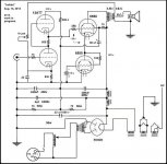
Since you show an 8R speaker, I would suggest connecting it to the 8R tap rather than the 16R tap, and connect the bottom connection to ground and use the top 16R tap for feedback.
Place a resistor between the feedback tap of the transformer and the cathode of the bottom 12AX7.
Hi, I tried it with the 3.5k transformer I have and it works great. Thank you very much for that.
The rest of the amp stays the same unless someone can talk some sense into me.
O.K., now it moves to my blog. -Fred
0 to 40 kHz sweep with the 16 ohm tap feedback:
0 to 40 kHz sweep - YouTube
2 kHz square wave with adjustment of the return pot:
6550/12AT7 direct coupled amp with feedback from 16 ohm 2 kHz square wave with resistor adjustment - YouTube
Attachments
Hi, I tried it with the 3.5k transformer I have and it works great. Thank you very much for that.
The rest of the amp stays the same unless someone can talk some sense into me.
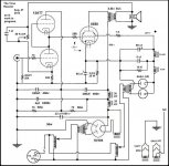
In your present schematic the grid of the input tube will float if there is no signal source plugged into the amplifier, or if the signal source has a capacitor in its output. This could lead to problems, especially since you have direct coupling to the output stage. A resistor down to ground would take care of this.
Also, your 1K pot for adjusting the feedback will also make large changes to the operating point for the input tube.
Chris
Last edited:
Hi, I tried it with the 3.5k transformer I have and it works great. Thank you very much for that.
The rest of the amp stays the same unless someone can talk some sense into me.
I am wondering also what is your intention with the 0.22uF bypass capacitor across the 830 ohm cathode resistor on the input tube? The capacitor has a reactance of around 7K ohms at 100Hz, falling to about 36 ohms at 20KHz. So its reactance is varying between being a lot higher than the cathode resistor at low audio frequencies, to being a lot lower than the cathode resistor at high audio frequencies. This means you will have a big inbuilt frequency dependence across the audio spectrum. It will also make the effect of the feedback strongly frequency dependent. Is this really what you are wanting to achieve?
Chris
Hi Chris. Thank you for hanging in with me on this and thank you for your patience with me.
Yes, the floating grids are a bad habit of mine. I'm waiting for a line input step up transformer to give the grid a ground reference and to improve the sensitivity a bit since my soundcard is maxed out.
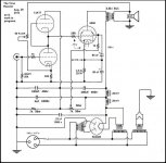
I left a ground connection on the output that is no longer there. The updated schematic is below with the ground connection removed.
My intent was to raise the dip in frequency response left by the high output impedance. But I see, and can hear, a reduction in distortion when I remove it. I think if I can even out the frequency response another way the system will sound very refined. I have not seen an output wave that clean on something of mine except for open loop single stages.
All I can think of at the moment is a parallel network with the output of the type I've read that Nelson Pass recommends. I'm sure my output impedance is not quite as high as his solid state amps with the series resistor so some adjustment will be necessary.
I intend to eventually remove it. But when it is removed, doesn't the inclusion of the output transformer in the feedback loop also make the feedback frequency dependent? How does a person make sure that all the negative feedback stays negative across the frequency spectrum with phase shifting taking place?
I understand I'm probably not asking for a small bit of advice.
I really appreciate you taking the time to ask me these questions. You've improved my project and given me a lot more to think about. I regret not being able to implement it all tonight but this next bit with the frequency response is going to take some head scratching and cut and try etc. etc. -Fred
In your present schematic the grid of the input tube will float if there is no signal source plugged into the amplifier, or if the signal source has a capacitor in its output. This could lead to problems, especially since you have direct coupling to the output stage. A resistor down to ground would take care of this.
Chris
Yes, the floating grids are a bad habit of mine. I'm waiting for a line input step up transformer to give the grid a ground reference and to improve the sensitivity a bit since my soundcard is maxed out.
Also, your 1K pot for adjusting the feedback will also make large changes to the operating point for the input tube.
I left a ground connection on the output that is no longer there. The updated schematic is below with the ground connection removed.
I am wondering also what is your intention with the 0.22uF bypass capacitor across the 830 ohm cathode resistor on the input tube?
My intent was to raise the dip in frequency response left by the high output impedance. But I see, and can hear, a reduction in distortion when I remove it. I think if I can even out the frequency response another way the system will sound very refined. I have not seen an output wave that clean on something of mine except for open loop single stages.
All I can think of at the moment is a parallel network with the output of the type I've read that Nelson Pass recommends. I'm sure my output impedance is not quite as high as his solid state amps with the series resistor so some adjustment will be necessary.
It (the bypass capacitor) will also make the effect of the feedback strongly frequency dependent.
I intend to eventually remove it. But when it is removed, doesn't the inclusion of the output transformer in the feedback loop also make the feedback frequency dependent? How does a person make sure that all the negative feedback stays negative across the frequency spectrum with phase shifting taking place?
I understand I'm probably not asking for a small bit of advice.
I really appreciate you taking the time to ask me these questions. You've improved my project and given me a lot more to think about. I regret not being able to implement it all tonight but this next bit with the frequency response is going to take some head scratching and cut and try etc. etc. -Fred
Attachments
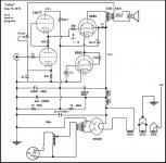
I left a ground connection on the output that is no longer there. The updated schematic is below with the ground connection removed.
Now you're more or less back to the peculiar "feedback" that you were using originally. I think you would be much better off with some more conventional type of feedback arrangement, which would be much more controllable and predictable. Whatever effect you are getting at the moment is the result of haphazard and unpredictable properties of the inter-winding capacitance and leakage between primary and secondary of the output transformer. That is really no basis for a solid amplifier design, I feel.
By the way, one sometimes sees the argument that one side of the OT secondary should be grounded for safety reasons. Otherwise, if there were an insulation breakdown that led to a short circuit from primary to secondary, it could take the speaker cable and speaker up to full B+ voltage.
Chris
The degree of feedback is also affected by the capacitance between loudspeaker and it wiring to the amplifier to earth. It form a with the interwinding capacitance a volta capacitive divider whose ratio is highly variable with physical layout, air humidity and position to earth, making it more unpredictable, not only in ratio but also in phase.
Hi Osvaldo de Banfield and Chris. I can see the evidence of what you guys are talking about. I really appreciate the explanation. It seemed to be delivering some of what I want so I thought I would continue to experiment with it. The safety issue has finally totally sold me on disconnected my feedback scheme and not bothering with it.
I connected it as shown below and it certainly has taken care of the issues of the previous feedback arrangement but of course there are now other issues. I can't imagine a feedback loop that includes the output transformer could be so simple and still be affective. Isn't there phasing issues even if they are more stable phasing issues?
I certainly appreciate the advice I've received. Thank you. -Fred
Attachments
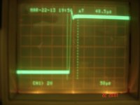
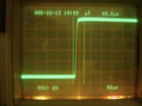
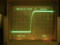
To modify phase angle in the feedback loop, a way to do it is to add a capacitor in parallel to the resistor from output to the cathode. The right value of it depends on several facts, buy an easy way to adjust it is as follow: add an oscilloscope to the load, in parallel with it. Place a square voltage signal at the input of the amp, and adjust the level of it to a value that be in the normal input range of it, say, no grid current nor saturation of current plate in no one of the stages. Adjust the capacitance and or the pot you placed between cathode and transformer to see the best wave at oscilo, without ringing or prominent slope at the rise and fall traces.
This more or less is the procedure to adjust close loop bandwidth.
The ideal adjust must be something like this photos: at first with few compensation, two is the best and three is overcompensated.
This more or less is the procedure to adjust close loop bandwidth.
The ideal adjust must be something like this photos: at first with few compensation, two is the best and three is overcompensated.
Attachments
Last edited:
Sorry about my insistence, but the circuit looks very strange. The lower power tube is acting like a CCS, without bypass, so the gain off the stage is very low, perhaps lower than 1 (0dB). I would definitively convert the stage in a WCF with better results, and better exploitation of the power tubes.
Hi Osvaldo de Banfield and Chris. I can see the evidence of what you guys are talking about. I really appreciate the explanation. It seemed to be delivering some of what I want so I thought I would continue to experiment with it. The safety issue has finally totally sold me on disconnected my feedback scheme and not bothering with it.
I connected it as shown below and it certainly has taken care of the issues of the previous feedback arrangement but of course there are now other issues. I can't imagine a feedback loop that includes the output transformer could be so simple and still be affective. Isn't there phasing issues even if they are more stable phasing issues?
I certainly appreciate the advice I've received. Thank you. -Fred
Your grounding of one side of the OPT secondary, and the removal of the 0.22uF cathode bypass capacitor, are great improvements!
However, you do now have another issue I raised for an earlier version of your schematic, namely that as you adjust the feedback pot. you will be altering the DC operating point of the input tube, and hence, since you have direct coupling to the output stage, this will in turn affect the DC operating point of the output stage. And the effect could be large; if you were to set the 1K pot. to maximum feedback (i.e. zero resistance), then the cathode of the input tube would essentially be directly at ground potential (just through the rather tiny DC resistance of the OPT secondary and speaker in parallel). So at the maximum feedback setting the input tube will essentially have Vgrid=Vcathode, and hence will be strongly conducting.
Do you really need as much feedback as you are now getting? After all, you had previously been using that 1K pot. in the feedback at a time when your OPT secondary was otherwise floating, and so you would have been getting no sensible feedback worth speaking of. Now that you have a properly grounded OPT secondary, you are feeding back a hefty output signal. I think usually the value of the resistor from OPT output to input tube cathode would be chosen to be large compared to the value of the cathode bypass resistor. (And its value would, if necessary, be chosen in conjunction with the value of the cathode bypass resistor so that the paralleled combination of the two would give the desired overall cathode bypass resistance.)
Anyway, it seems to me you should be deciding on your desired DC operating point for the input tube, and not providing a feedback adjustment pot. that, as an unintended side effect, wildly alters what that operating point is.
And I would still be nervous about that grid on the input tube which, with your present schematic, would be floating if the audio input to the amplifier were unplugged. Again that could lead to a wild and unpredictable change to the DC operating point of the input stage, and hence, via the DC coupling, to the operating point of the output stage. Whether it could do damage is perhaps unclear, but for the mere cost of a 100K resistor to tie the input grid voltage to ground potential, it doesn't seem worth the risk of finding out.
Chris
Last edited:
Oh my goodness thank you guys and I'm grateful for your insistance. I have only so far replaced the 1k pot in the feedback loop with a 200k pot and connected a small pf range capacitor which looked to help the ringing.
I can see now that the speaker network and feedback resistor are in parallel with the cathode resistor of the 1st tube. I've seen that Mullard cuircuits have different specified cathode resistors for whether an 8 ohm or sixteen ohm speaker is connected.
The feedback compensation technique you describe is very appropriate to my abilities. Many years ago I was trying to draw a loadline and my Dad told me I could connect a pot as the load and sweep it with a signal and look at the waveform. I was up and running and never looked back. I hope one day calculate things as well… I know there is more message below but I will have to sign out here. Thank you Chris and Osvaldo de Banfield. -Fred
I can certainly hear and see the improvements from this! I will remedy the floating grid when I return to it as well as try the WCF idea. I've had a few minutes to play with it but should have lots soon.
I hope my reply is OK. I'm replying on my phone and it's not going so well...
I hope my crazy idea will become more like a proper working and good sounding amplifier. I'm already more than happy with the volume it is putting out.
OK, try our suggestions and enjoy.
I must add that I never used the WCF as output stage yet, but lots of guy's used it and I tried it as a line driver luckily.
Keep us posted.
Hi. I was unable to get it work OK. I think it's beyond my skills. I understood that it was untested. I also have not been able to make a Broskie idea work out either. Thank you so much for the idea and it's in my sketchbook.
I've been having fun with the compensation technique but I need more small value capacitors to play with. I see from your illustrations the best I can do is overcompensate but I'm happy with that for now. -Fred
As I was playing with the WCF on the output, I came up with this (pic below).
I'm unclear as to how high a voltage I should have the screen. As I increase the screen voltage the grid on the 6550 goes more negative. I found a balance but I don't know if it's optimal. I believe I'm near the center of the loadline since as I increase the volume the clipping is symmetrical within a volt or so and the loudness is quite good.
It puts out a nice even response from 0 to 40kHz again and sounds very nice with no audible clipping or problems with music.
My intent with the separate screen supply is to reference the screen of the 6550 with it's cathode and make any drift due to maybe plate/heater heat and draw from B+ to have less effect on the gain. It doesn't seem to get louder as I listen so I believe it's working.
I had a few chokes lying around so I thought I'd just try it.
Thanks for looking. -Fred
Attachments
1) 0 Hz through a transformer is formerly impossible, transformers do not allow DC voltages nor currents.
2) Each 6AX4 draws about 1.2 amper in its heaters, and a dedicated transformer exclusively to powering the screen is a waste of energy and space. The circuit can work fine without the screen supply, and using the same as the plate circuits. In case of the screen supply is active and the plate one doesn't, screen grid will be destroyed quickly.
Only a couple of opinions, no more.
1) 0 Hz through a transformer is formerly impossible, transformers do not allow DC voltages nor currents.
I won't write 0 - whatever anymore.
I'm always embarrassed to read what I write but It's very nice to post my things and see what happens.2) Each 6AX4 draws about 1.2 amper in its heaters, and a dedicated transformer exclusively to powering the screen is a waste of energy and space. The circuit can work fine without the screen supply, and using the same as the plate circuits. In case of the screen supply is active and the plate one doesn't, screen grid will be destroyed quickly.
I took off the extra supply. I'm still referencing the screen to the cathode though.
Incidentally, the extra supply helped me find an operating point pretty easily. But I was sweating powering on and off trying to keep straight which to power up first. I notice no change in operation using the regular supply for the screens so and I'm glad to get my parts back too.
Only a couple of opinions, no more.
Thank you for that. Below is pic of a 2 kHz square wave into a resistive 8 ohm load. I'm pretty proud of it even though it looks like there is a bit of ringing. I think I will be sad if the work on it is ever done.
I really like the sound of this amp! It's rocking my world.
Thank you. -Fred
Attachments
- Status
- This old topic is closed. If you want to reopen this topic, contact a moderator using the "Report Post" button.
- Home
- Amplifiers
- Tubes / Valves
- Direct connected madness