
If you are saying what I think you are saying then this is unnecessary. DC in a transformer winding is only a problem when it is unbalanced by DC in another winding. Half-wave rectification of a secondary is fine. Applying DC to a transformer is a bad idea. Taking DC from a transformer is fine, as the primary will balance it away. The result will be a little DC on your mains supply, but a bias supply will not create a problem.mr2racer said:All I want it to do is bleed off the positive voltage to ground to keep the DC out of the transformer.
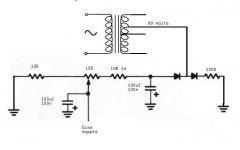
The transformer secondary center tap is connected to ground. The negative bias supply is connected to the output tube grids. And the positive 'waste' is connected to ground. When I say to the left of the 80 volt input I mean the left hand diode and to the left of it. That is the original circuit.
On another thread some people condemned the half wave rectifier. Because it left DC on the secondary winding? They suggested a full wave bridge instead. I couldn't find an example in my books so I figured this might work to bleed off the positive voltage without any current to ground.
A bridge would require a dedicated winding which is not available in the MKIII power transformer. The real benefit of full wave rectification over half wave in a low current application like this is the 120Hz ripple frequency which is easier to filter than 60Hz ripple. Modern electrolytics make this less of an issue as they are easily and inexpensively upsized.
First, its a bias supply so I don't need current. ..
You need current flowing thru the adjustment pot (to ground) for the voltage to be adjustable. Voltage drop thru a resistor/pot occurs only if there is current.
Yes there is no current flowing out the wiper.
One of those guys was me  . The reason I dislike half wave rectification, is because of the double time the cap is allowed to discharge, giving lower ripple frequencies at a higher current draw. It's also influenced by a changing load much worse. I know this is all less of a concern with a bias supply, but why skimp something like this. Any kind of DC offset never was an argument to advice FWR. The given schematic isn't going to do you any good. But why not use a full wave bridge??
. The reason I dislike half wave rectification, is because of the double time the cap is allowed to discharge, giving lower ripple frequencies at a higher current draw. It's also influenced by a changing load much worse. I know this is all less of a concern with a bias supply, but why skimp something like this. Any kind of DC offset never was an argument to advice FWR. The given schematic isn't going to do you any good. But why not use a full wave bridge??
Last edited:
See post # 15, no available space in the Dynaco MKIII chassis for a dedicated transformer, the stock power transformer has a single tap for a half wave rectifier.
Yeah I know, I should have been more clear. I meant forget about the dedicated tap and do a new full wave rectified version from the B+ taps. There are several ways to do this, (almost) without loading the B+. Dedicate bridge with series dropping resistor being the simplest IMO.
But it might be to much of a hassle for only a small improvement. I wasn't aware of the single tap when commenting of the half wave rectification.
Last edited:
This from a guy with little confidence in his own ability. I thought this a neat solution. A half full wave bridge. Works with the single bias tap. Is limited by the large resistor to almost no current on the positive side. If I understand this correctly the voltage will pass the resistor to ground without any noticeable draw on the winding. And it would only cost a diode and a resistor.
Attachments
I understand now. Using a halfwave means you have a series of pulses, in this case below zero, punctuated by a series of gaps where the diode doesn't conduct. In a full wave you have a continuous series of pulses without gaps. So the the halfwave depends more heavily on the smoothing caps. So to optimize a halfwave you would want a fast diode and fast, read low ESR, caps. Correct?
- Status
- This old topic is closed. If you want to reopen this topic, contact a moderator using the "Report Post" button.
- Home
- Amplifiers
- Tubes / Valves
- Someone Told Me This Wouldn't Work?