Greetings all. I have a pair of Altec 1570B amplifiers that I have been slowly rebuilding. I now have them up and screaming and I enjoy them a lot. My question is this: There is a 1000 volt 6uF capacitor in the B+ supply (C8 on the schem) that is a bit leaky. I read on another forum (cant remember where) that this cap value should not be changed because it is a "tuned circuit". Looking at the schematic it looks like a straightforward tube rectified LC supply to me. I know that the cap value for rectifier tubes cannot be too high but I have 2 new 7.5uF caps to replace the 6uF caps. An extra 1.5uF is not enough to harm the tubes but I am puzzled about this tuned circuit bit. Was it just someone blowing smoke or do they know/see something I don't?
Anyway, should I change these caps and bump up the extra 1.5uF?
Attached is a schematic. Fire away, inquiring minds want to know!
Anyway, should I change these caps and bump up the extra 1.5uF?
Attached is a schematic. Fire away, inquiring minds want to know!
Attachments
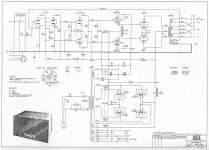
It's hard to read the writing on the schematic, but it looks like C8 is the electrolytic right after the choke? If so the tolerances on old electrolytics are +/- a bunch so you are probably OK.
On the other hand I have seen HV power supplies used in old Motorola radio transmitters that did use a resonant element. The choke had a cap connected directly across it and there was also a cap from either side to ground. All three caps were in the same can and they were PIO. The schematic warned that the cap and choke were to be replaced as a pair if either one failed.
If it was my choice, I would try the 7.5uF caps.
Yes it is the cap right after the choke. I dont see anything "tuned" about this power supply. I will give it a go!
Just like the hungry computer said: "Thanks for your input"!
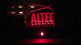
These old beasts are really great but they sure were ugly! I did a little work on the cosmetics by blacking the entire thing out (except for the big, beautiful tubes of course!) and adding an edge lit plexi front panel I engraved with the Altec logo.
They sure look cool at night!
Just like the hungry computer said: "Thanks for your input"!
These old beasts are really great but they sure were ugly! I did a little work on the cosmetics by blacking the entire thing out (except for the big, beautiful tubes of course!) and adding an edge lit plexi front panel I engraved with the Altec logo.
They sure look cool at night!
Attachments
I know that the cap value for rectifier tubes cannot be too high but I have 2 new 7.5uF caps to replace the 6uF caps. An extra 1.5uF is not enough to harm the tubes but I am puzzled about this tuned circuit bit. Was it just someone blowing smoke or do they know/see something I don't?
Anyway, should I change these caps and bump up the extra 1.5uF?
It is an incidental tuned circuit, an L-network to be precise. The only difference between L-network and LPF is the Q-factor. All proper LPFs (Butterworth, Chebychev, Bessel) all have Q < 1.0. That's not an easy thing to accomplish with the usual values of L and C encountered in any ripple filter. (I calculated the values for a Chebychev characteristic and came up with huge values for L and small ones for C -- totally impractical). You need to get that resonant frequency way below the audio band. For my projects, Fo= 4.0Hz, with a Q~= 13. That would make for a nasty filter bounce, but it's highly unlikely the filter would see 4.0Hz. That's 2.3 octaves below the 20Hz bottom of the audio band.
In this case, replacing a 6.0uF filter capacitor with a 7.5uf unit will drive that resonant frequency even lower, give you somewhat better attenuation of the AC ripple frequencies. Besides, electrolytic capacitors aren't that accurate in the first place when it comes to actual capacitance v. nominal capacitance. It won't cause problems.
On the other hand I have seen HV power supplies used in old Motorola radio transmitters that did use a resonant element. The choke had a cap connected directly across it and there was also a cap from either side to ground. All three caps were in the same can and they were PIO. The schematic warned that the cap and choke were to be replaced as a pair if either one failed.
There was once a vogue for doing that: making the inductor into a parallel resonant trap. However, that's a classic SLAGIATT: sure, it will attenuate the hell out of the fundamental of the AC ripple, but ripple has a large harmonic content, and those harmonic frequencies are going to see a much lower impedance from the parallel tuned circuit than would be the case for an LC LPF. It will let more of those ripple harmonics through, and you don't want those polluting the DC rail.
Subsonics could come from a turntable, or from mains voltage variations. Fortunately, the load (i.e. the amplifier circuit) adds significant resistive damping so the actual Q is likely to be much lower than your calculation (based on choke resistance?). Still needs thinking about, though, but often ignored in PSU design - especially by the type of designer who think that if something is good then more of it must be better?Miles Prower said:For my projects, Fo= 4.0Hz, with a Q~= 13. That would make for a nasty filter bounce, but it's highly unlikely the filter would see 4.0Hz. That's 2.3 octaves below the 20Hz bottom of the audio band.
Subsonics could come from a turntable, or from mains voltage variations. Fortunately, the load (i.e. the amplifier circuit) adds significant resistive damping so the actual Q is likely to be much lower than your calculation (based on choke resistance?). Still needs thinking about, though, but often ignored in PSU design - especially by the type of designer who think that if something is good then more of it must be better?
Since I don't have a turntable, it's not a prob. If I did have one, I'm sure the pre (either self designed or other) would include a rumble filter to keep that garbage out of the amp. Here are the results of the actual filter values I used for an LC ripple filter:
L= 7.0H
C= 220uF
R= 2K8 (350Vdc rail; Il= 125mA)
For a second order LCR LPF:
A(w)= [(1 - LCw^2)^2 + (wL/R)^2]^-0.5
Xfer equation for series L at the input, with parallel load R and C at the output.
That peak occurs at 4.0Hz, with the -3.0db frequency at 6.3Hz. That resonance peak is well away from the bottom of the audio band to not be a prob.
A proper LPF with Q < 1.0 would need L ~= 100H and C= ~14uF. A 100H inductor that could handle 125mA would be very large and very heavy. Big capacitors are both easier and cheaper than big inductors.
Attachments
OK. In case of difficulty a CR 'snubber' could be added in parallel with the cap to further damp the subsonic resonance.
That won't work, since these snubbers dampen out high frequencies, not low ones. At DC, the snubber simply disappears, and becomes increasingly visible as frequencies increase, and Xc decreases.
The only way to dampen out that low frequency resonance is to decrease the load resistance, and that just makes for worse ripple, and wastes a whole bunch of power. Your only options are RC ripple filtration (half as effective, and compromises voltage regulation -- useful where you have relatively constant load currents, and excessive voltage capability) or using big reservoir capacitors (not possible with vacuum diodes, due to limited Isurge capability, and inadvisable when using vintage PTXs since these weren't designed with huge Isurge in mind). You could also try active decoupling if it's gonna be a problem.
Last edited:
A snubber could work at 4Hz. It will have less effect at higher and lower frequencies, but there its effect is not needed anyway.
For example, put 100uF in series with 400R then place in parallel with the 220uF cap. At 4Hz this looks like 50uF in parallel with 800R (if my arithmetic is right). The 50uF slightly drops the resonance frequency, but not by much. The 800R damps the resonance as it appears in parallel with your 2k8 load.
For example, put 100uF in series with 400R then place in parallel with the 220uF cap. At 4Hz this looks like 50uF in parallel with 800R (if my arithmetic is right). The 50uF slightly drops the resonance frequency, but not by much. The 800R damps the resonance as it appears in parallel with your 2k8 load.
- Status
- This old topic is closed. If you want to reopen this topic, contact a moderator using the "Report Post" button.
- Home
- Amplifiers
- Tubes / Valves
- Tuned Circuit?