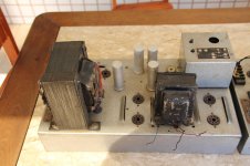
I want to revamp two monoblock amplifiers using four EL34 tubes in the output. I would like to maintain the appearance and arrangement of valves, but use a more modern layout. I need help to identify the scheme that could be used while maintaining the same original tubes and their positions. I'll redo the whole set, including rebuilding the power transformers and output transformes.
Any help is welcome. Below, some photos of the amplifiers:
Any help is welcome. Below, some photos of the amplifiers:
Attachments
Last edited:
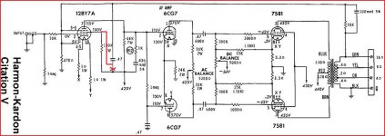
IMO, you're dealing with a variation on the "classic" Mullard 5-20 theme. The best "vintage" Mullard circuit amp I'm familiar with is the Harman/Kardon Cit. 5. High gm in the small signal complement provides protection against HF error correction signal induced slew limiting, in circuitry that employs a GNFB loop.
You can take the Cit. 5 idea and upgrade it by using an ECC99 as the LTP phase splitter and using a constant current sink (CCS) in the splitter's tail, instead of a resistor. The CCS forces symmetry between the 2 splitter halves.
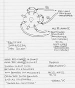
Among current production 5AR4/GZ34s, the Sovtek is best. However, the Russian tube can get shaky towards the top of the documented voltage range. SS diodes in series with the 5AR4 anodes provides the extra PIV headroom needed. The graphic shows 1N4007s, but they are VERY noisy. Instead, use UF4007s, which are quieter. The vacuum rectifier blocks SS diode switching noise, but less noise, from the very beginning, has to be better.
BTW, the 12AU7/ECC81 is a non-linear POS. If you want to stay close to the original (as best as can be determined) use a 6FQ7/6CG7.
You can take the Cit. 5 idea and upgrade it by using an ECC99 as the LTP phase splitter and using a constant current sink (CCS) in the splitter's tail, instead of a resistor. The CCS forces symmetry between the 2 splitter halves.
Among current production 5AR4/GZ34s, the Sovtek is best. However, the Russian tube can get shaky towards the top of the documented voltage range. SS diodes in series with the 5AR4 anodes provides the extra PIV headroom needed. The graphic shows 1N4007s, but they are VERY noisy. Instead, use UF4007s, which are quieter. The vacuum rectifier blocks SS diode switching noise, but less noise, from the very beginning, has to be better.
BTW, the 12AU7/ECC81 is a non-linear POS. If you want to stay close to the original (as best as can be determined) use a 6FQ7/6CG7.
Attachments
Duttman,
Thank you for your quick replay. You gave me a great tip and I'll give it a try: mix SS components and tubes to improve the performance of the rectifier circuit.
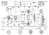
I will redraw the circuit based on the monoblock components installed. Thus, we can compare the circuits used in this unit with Mullhard 5-20 theme.
Thank you for your quick replay. You gave me a great tip and I'll give it a try: mix SS components and tubes to improve the performance of the rectifier circuit.
I will redraw the circuit based on the monoblock components installed. Thus, we can compare the circuits used in this unit with Mullhard 5-20 theme.
Nice "Look and feel"
Hello JonSnell,
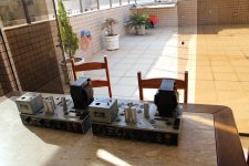
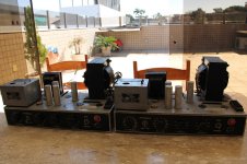
This amp looks like a tank. Strong and his presence is noticed in any environment. Reminds me of my childhood, when spent hours listening to rock and rool. The more valves had the device, the more I was impressed. For this reason I wish to maintain the original appearance.
A nice piece of Dutch workmanship.
Hello JonSnell,
This amp looks like a tank. Strong and his presence is noticed in any environment. Reminds me of my childhood, when spent hours listening to rock and rool. The more valves had the device, the more I was impressed. For this reason I wish to maintain the original appearance.
Internet
Before posting here in this forum, I did extensive research on the internet and could not find the schematic of this amplifier. But I will rebuild the schematic based on the installed components. As the amp is very old, it is likely that the monoblocks have changed over the years. Once able to complete the layout, I'll put a copy here, so maybe you can help me to set the project to revamp.
Before posting here in this forum, I did extensive research on the internet and could not find the schematic of this amplifier. But I will rebuild the schematic based on the installed components. As the amp is very old, it is likely that the monoblocks have changed over the years. Once able to complete the layout, I'll put a copy here, so maybe you can help me to set the project to revamp.
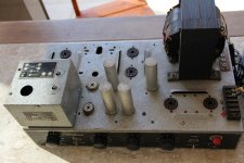
Both amps look like they had Output Transformers mounted in between the 4 Octal (big 8 pin) tube sockets spaced far apart in the back left where the EL34's go. You shouldn't have to rebuild any of the transformers normally! Maybe just some cleaning and paint.
Anyway just wondering what they look like as the PS one is sure big.
You actually need a schem for PPP EL34. I think there are some good ones on this site and maybe diytube. They may be for 6550?KT-88 tubes, but should work fine.
Anyway just wondering what they look like as the PS one is sure big.
You actually need a schem for PPP EL34. I think there are some good ones on this site and maybe diytube. They may be for 6550?KT-88 tubes, but should work fine.
Last edited:
Yes, there's definitely a void in the grime between the two pairs of EL34. And holes for the wires. That'd be a bummer. @apnneto: why not post a frontal pic of the amp and the innards? I'm sure there's not a lot in it and reverse engineering it would be fairly straightforward. Maybe there's info after all. It for sure isn't manufactured in the Netherlands. But then Philips was a multinational even before second WW. There must have been factories in Brazil in the fifties.
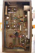
New Images
At first, I was thinking about redoing the whole circuit, regardless of what was installed. But now, I will try to improve the existing circuit. I will use the software Eagle to draw the schematic and post it here to see what could be improved.
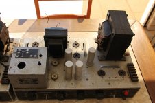
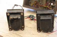
The output transformers were added in the photos. I removed them to make some measurements, because one of them probably underwent repairs.
The amplifier has tone control and selection for photocell and microphone.
Nowadays, "Philips do Brazil" mainly produces lamps and electrical components. I had no success in contacting them to get the original manuals and schematics of the amplifiers. I believe that they should not have them.
At first, I was thinking about redoing the whole circuit, regardless of what was installed. But now, I will try to improve the existing circuit. I will use the software Eagle to draw the schematic and post it here to see what could be improved.
The output transformers were added in the photos. I removed them to make some measurements, because one of them probably underwent repairs.
The amplifier has tone control and selection for photocell and microphone.
Nowadays, "Philips do Brazil" mainly produces lamps and electrical components. I had no success in contacting them to get the original manuals and schematics of the amplifiers. I believe that they should not have them.
Attachments
Last edited:
Phew! At least the XFMRs are still there. You may want to leave them as is only redo the covers with black paint. Must be local production as Philips never used transformer covers.
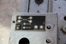
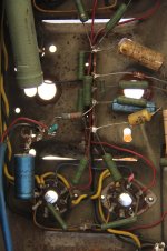
It looks like someone already had a go at it. The black caps are not original, nor is the white ceramic resistor. The green resistors with the value printed on them are also not Philips but prolly original. The mustard capacitors are famous and original as are the blue electrolytics. The resistors in the power supply look tired and should be replaced. Can't figure out the GZ34s (parallel or something else?). Oh, and all caps on the top side of the chassis (big cans) will be toast.
A shot from the front panel would help, as some more closeups. The cover over the tone control (ECC83, prolly standard Baxandall) is in the way as well. And the EF86 preamp is completely hidden by the shielded volume control (at least I think that's what it is). Oh, stick to one amp when you make more piccies. The better looking one...
Last edited:
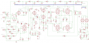
After awhile, I'm back to this project. I thought it was a Mullard 5-20 mod, but after drawing the wiring diagram from the circuit, I know that this is not the amp.
Some days ago I was starting to work on a ground plan, and then I had to stop.
Now I'm totaly lost. I searched the net looking for similar schemes and informations about this amp but had no success.
So, I have several questions, like these:

More photos here.
Some days ago I was starting to work on a ground plan, and then I had to stop.
Now I'm totaly lost. I searched the net looking for similar schemes and informations about this amp but had no success.
So, I have several questions, like these:
- What type of source can I connect in the audio inputs? Too much gain ???
- Is it better than Mullard 5-20? Or should I forget it and go with 5-20?
- How the pots connected to 'line in' on EF86 works? Are they like a mixer?
- The original output transformer was 800 ohms. One was broken. I'm using a spare pair with 4/8 and 16 ohms. How should I modify the feedback loop?
More photos here.
Attachments
Last edited:
You have an unique amplifier, imo, you should not modify it to Mullard or anything else, it should be restored (sans the OPT) to the original condition as much as possible. Is there a model number shown on the front plate (on the box containing the EF86)? Also, what are the control functions on the front panel, from left to right? Since the OPT is gone, you are free to re-configure the output to work with modern off-the-shelf one - but it's still going to be a big one though. How much power do you need?
Last edited:
The inputs seems to accept two sources with one vol.cotrol.Nothing in the middle ,one direction for each source.
In the bottom the two inputs have something like a (adjustable) phantom supply.Very sensible, condensor-mike ?
There are some errors in the schematic but make not to much about it,Herman Karton make them too .
I indicated with a red "circle" where I found something wrong.
The use of the two Si-diodes is not very clear.
Mona
In the bottom the two inputs have something like a (adjustable) phantom supply.Very sensible, condensor-mike ?
There are some errors in the schematic but make not to much about it,Herman Karton make them too
.I indicated with a red "circle" where I found something wrong.
The use of the two Si-diodes is not very clear.
Mona
Attachments
You have an unique amplifier, imo, you should not modify it to Mullard or anything else, it should be restored (sans the OPT) to the original condition as much as possible. Is there a model number shown on the front plate (on the box containing the EF86)? Also, what are the control functions on the front panel, from left to right? Since the OPT is gone, you are free to re-configure the output to work with modern off-the-shelf one - but it's still going to be a big one though. How much power do you need?
I thought about Mullard 5-20 because there are a lot of information out there and the tubes are all the same, as the power transformer. But for this unit I know nothing.
I think it was used as a PA on a cinema or theater. The inputs are microphone, pickup and two source in for audio projector. But I know nothing about this circuit and the quality of the sound.
But as you suggested, I will try to restore to its original condition.
There is a model number but I tried to find any information about them with no success. The model is Philips type 3860/24, serial number 192, 275 watts.
The controls on the front, from left to right, are:
- Volume control for output EF86 and connection to ECC83;
- Switch from Mic/Pickup Input (down) and line 1 and 2 (up)
- Volume control for inputs Mic/Pickup (half for each one)
- Treble
- Bass
- Power On
For power output anything between 50 and 75 watts are welcome. I will probably buy a pair of OT for UL use.
I'm still trying to find reviews for this circuit.
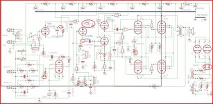
There seem to be some missing connections around V8B on your schematic. I agree with restoring the amp rather than modifying it.
Your are right! Thank you.
The inputs seems to accept two sources with one vol.cotrol.Nothing in the middle ,one direction for each source.
In the bottom the two inputs have something like a (adjustable) phantom supply.Very sensible, condensor-mike ?
There are some errors in the schematic but make not to much about it,Herman Karton make them too
I indicated with a red "circle" where I found something wrong.
The use of the two Si-diodes is not very clear.
Mona
Thank you for your help.
I will make the adjustment. And you are right about the vol. control: one direction for each source, but this is true only for Mic/Pickup (the two source in on the bootom). For EF86, the output is connected to one vol. control.
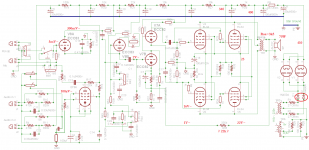
Now here is the schematic with my suposed adjustements.
Mona
Very good, thank you a lot.
I will turn on one monoblock e measure the voltage and check with your values. They seem to be very close.
The feedback resistor is 33k (330k was wrong as the r22 that is 68 ohms/50w). But it was projected for 800 ohms at the output of OT. Now, which value should I use?
About the input of EF86, what kind of source can I connect? I tried a CD input with a passive preamp but the gain is too high. Is there any mod that I can do to get better results?
About diodes, I included them as suggested on post #3.
I'm now working on the schematic!
Last edited:
- Status
- This old topic is closed. If you want to reopen this topic, contact a moderator using the "Report Post" button.
- Home
- Amplifiers
- Tubes / Valves
- Need Help - Monoblock Power Amplifier EL 34