In ultra-linear mode, it seems like many designs I have seen have the potential to exceed the maximum rated screen voltage when a signal is applied, but are fine at idle.
The DC voltage at idle is what the datasheet specs as max. However, most typical applications for ultra-linear circuits in various tube datasheets allow the maximum peak sine wave to go above the screen voltage rating according to my calculations.
Is this OK?
The DC voltage at idle is what the datasheet specs as max. However, most typical applications for ultra-linear circuits in various tube datasheets allow the maximum peak sine wave to go above the screen voltage rating according to my calculations.
Is this OK?
I've seen circuits that use a coupling cap from the screen UL transformer tap to the screen grid. And the screen grid also having a resistor going to a screen voltage supply. Thing is, this resistor will look like a load to the output transformer, robbing some power from the output. I've also seen output transformers having a separate UL winding, so you could feed the screen grids directly without the loading of a screen resistor, but that adds expense. And another solution is to use a screen resistor between the UL tap and the screen grid (to drop the voltage for the screen grid), with a bypass cap across the resistor, which looks to be the best answer.
We have established that the screen voltage peaking above maximum ratings is an issue. What does concern me now is plate voltage exceeding the maximum rating with a signal swing.
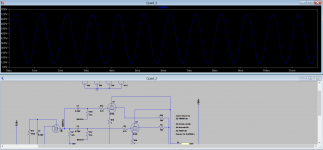
The maximum B+ rating for a 6550 is 660 volts. The design in the screenshot uses 420 volts B+. It uses KT88 tubes with a maximum plate voltage of 800 volts. At full power, each plate peaks at 720 volts, within the rating. For a 6550, the maximum rating would be exceeded by 60 volts when the signal peaks.
Just about every design I have seen does not take the plate issue into account (Even Carver, as he runs his idle B+ voltages almost at maximum). It appears they only thought about idle DC plate voltage.
Did I just have a major design flaw revelation or were tubes designed to peak above maximum ratings with a signal? For tests I like to run continuous waveforms at full power to guarantee reliability.
Attachments
Please take into account that the maximum ratings for the plate (anode) voltage is defined with idle plate current active. There exists a second maximum rating, unfortunately not documented in most of the datasheets today
Let us take as an example the EL34. In old specifications you will find 2 values
1. Ua max (idle) =800V
2. Ua max(Ia=0) =2000V
Here is the background: In PP basically one of both tubes is active, the plate voltage is going down, in parallel the PP OT the plate voltage of the other one is going up symmetrically but there is no plate current at that tube. So now assume a of a PP pair of EL 34 with an idle voltage of 800V with an PP OT of Raa=11KOhm.This is the typical EL34 class B design example. At full power the plate will swing between ~50V and 1550V.
As said above unfortunately in most of specs of today you will miss the second maximum rating mentioned above. But the tubes are able to handle this high level of plate voltage without plate current - otherwise no PP powerstage would work.
I've seen circuits that use a coupling cap from the screen UL transformer tap to the screen grid. And the screen grid also having a resistor going to a screen voltage supply. Thing is, this resistor will look like a load to the output transformer, robbing some power from the output. I've also seen output transformers having a separate UL winding, so you could feed the screen grids directly without the loading of a screen resistor, but that adds expense. And another solution is to use a screen resistor between the UL tap and the screen grid (to drop the voltage for the screen grid), with a bypass cap across the resistor, which looks to be the best answer.
Thanks for the suggested methods as I have been thinking along similar lines. You think I can replaced the resistor between UL tap and screen grid with a zener diode paralleling with a coupling cap? This way you can keep the screen voltage under control with the zener and having feedback into the screen with the cap?
Similar to the below circuit in this thread.
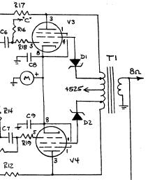
Why do you need the caps? The zeners alone in spice seem to cut it by themselves. The voltage across the zeners would be at the mercy of the breakdown, which seemingly does not make a rectifier into the screens. Spice seems to be playing tricks here, or my circuit analysis could be also.
Last edited:
Why do you need the caps? The zeners alone in spice seem to cut it by themselves.
Can a zener pass AC signal?
- Status
- This old topic is closed. If you want to reopen this topic, contact a moderator using the "Report Post" button.
- Home
- Amplifiers
- Tubes / Valves
- Screen Grid Peak Voltage