Miles, it sucks ? Can you elaborate why and potentially give me a clue why it could have burned down on a regular basis in my amps ?
What would be a better circuit which gets the job done in a reliable way ? anyone tried this http://www.tubecad.com/2009/04/blog0163.htm
What would be a better circuit which gets the job done in a reliable way ? anyone tried this http://www.tubecad.com/2009/04/blog0163.htm
Last edited:
Miles, it sucks ? Can you elaborate why and potentially give me a clue why it could have burned down on a regular basis in my amps ?
Look at the schemo again:
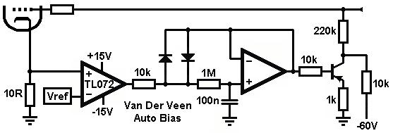
This is not a servo, there's no NFB control loop, it's just a rectifier + LPF. A true servo needs an integrator with feedback loop if there is to be any auto-correction. Van Der Veen doesn't know what in the hell he's discussing here.
What would be a better circuit which gets the job done in a reliable way ? anyone tried this Blumlein’s Garter Circuit Revisited
Go here: Clicky and check out the schemo. This shows how to implement a proper DC servo with a control loop around an integrator. Pretty standard, and it does auto-correct.
What is the difference actually? An integrator instead of a RC chain 1M/100n, and a MOSFET instead of BJT. Most probably a positive voltage caused by a running away tube damages the transistor, so a diode across it would save it. Also, may be the transistor must be rated for higher voltage.
Anyway, in both cases all that extra devices simulate a simple resistor in cathode shunted by a cap.
Anyway, in both cases all that extra devices simulate a simple resistor in cathode shunted by a cap.
Anyway, in both cases all that extra devices simulate a simple resistor in cathode shunted by a cap.
That's not what the OP asked about. He wanted to know about DC servos. As for TNEA, all the extra devices were included so's he could get four finals all pulling the same currents with one bias adjustment: the one that sets the Vref for the other three. Cathode bias pretty much requires matched finals for current balance, especially when toroid OPTs are used as these can't tolerate very much residual DC due to the closed nature of the core.
I prefer fixed bias finals with cathode/source follower grid drivers.
So I would proffer that there is no better configuration, because the intent is not to operate at conditions that stress the valves. Typically that would mean at levels close to, but below max design rated levels, assuming that stress did not occur from non-electrical mechanisms (eg. poor cooling, or excessive acceleration).When maximizing tube life, for each of the following tubes, is pentode or UL better?
Tube quality and luck would then likely determine what degradation mechanism kicks in first for each valve.
It's difficult to discuss single cases of failure and get any good insight, other that to showcase what excessive operating conditions should be avoided. A common failure observation, such as gross grid conduction causing thermal runaway could result from a variety of internal problems.
Circuit design that minimises peripheral damage seems worthwhile - but I don't think triode or UL or pentode mode intrinsically offers any particular benefit.
If you threw Mil-hdbk-217 at it, then I reckon triode mode would win - back to the future!
Correct. An RC filter is an integrator, and the whole system is a negative feedback loop. I think Miles may have been smoking something.What is the difference actually? An integrator instead of a RC chain 1M/100n,
Agreed; the transistor needs a base-emitter protection diode, or it is liable to degrade the junction, slowly, every time the circuit is switched on and the base is pulled above the emitter. This could explain why it happened after some months of usage.Most probably a positive voltage caused by a running away tube damages the transistor, so a diode across it would save it.
Last edited:
The circuit is not quite the same as just an RC or integrator.
The two diodes (in original ckt), across the input of the 2nd Op Amp, limit the relative integrator sampling to +/- 0.6V (the zero effectively determined by Vref). If Vref drifts out of range, then the circuit integrates the wrong place in the class aB tube current waveform. (I assume it has to stay within the small class a part.) Vref needs to be accurately centered in the class a part of the current waveform. This could be tricky to set up right and prevent drift with age or temperature.
--------------------------------
"So I would proffer that there is no better configuration"
(pentode versus UL or triode)
Ummm, not so sure about that. Take a look at this:
http://www.diyaudio.com/forums/tube...nificent-television-tubes-47.html#post4574408
Same Sweep tube, for same current output range (this would be class B for all cases and is full curve tracer plot coverage, ie below plate knees too):
standard -g1 drive leads to 900 mW avg. heating of grid 2
+g2 drive leads to 704 mW avg. heating of grid 2
+g2 + +g1 "Crazy Drive" leads to 22 mW avg. heating of grid 1 and 432 mW avg. heating of grid 2
I even tried "Crazy Drive" with some frame grid tubes and it works well. Half the grid 2 heating of g1 drive.
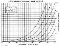
(a 26LX6 only requires +50V peaks on g2 to reach 0.5 Ampere plate current, and it's the most linear tube response curves you ever saw, and that's before any feedback, like UL or triode.)
-----------
For usual grid 1 drive scenarios:
One could also try a normally conducting rectifier/diode in series with the grid 2 to prevent arcing to the plate (when the plate is at 2 x B+). However, that might allow the grid 2 to go further positive than intended occasionally, due to secondary emission from grid 2 itself. So include some quench resistor across the diode to prevent that.
The two diodes (in original ckt), across the input of the 2nd Op Amp, limit the relative integrator sampling to +/- 0.6V (the zero effectively determined by Vref). If Vref drifts out of range, then the circuit integrates the wrong place in the class aB tube current waveform. (I assume it has to stay within the small class a part.) Vref needs to be accurately centered in the class a part of the current waveform. This could be tricky to set up right and prevent drift with age or temperature.
--------------------------------
"So I would proffer that there is no better configuration"
(pentode versus UL or triode)
Ummm, not so sure about that. Take a look at this:
http://www.diyaudio.com/forums/tube...nificent-television-tubes-47.html#post4574408
Same Sweep tube, for same current output range (this would be class B for all cases and is full curve tracer plot coverage, ie below plate knees too):
standard -g1 drive leads to 900 mW avg. heating of grid 2
+g2 drive leads to 704 mW avg. heating of grid 2
+g2 + +g1 "Crazy Drive" leads to 22 mW avg. heating of grid 1 and 432 mW avg. heating of grid 2
I even tried "Crazy Drive" with some frame grid tubes and it works well. Half the grid 2 heating of g1 drive.
(a 26LX6 only requires +50V peaks on g2 to reach 0.5 Ampere plate current, and it's the most linear tube response curves you ever saw, and that's before any feedback, like UL or triode.)
-----------
For usual grid 1 drive scenarios:
One could also try a normally conducting rectifier/diode in series with the grid 2 to prevent arcing to the plate (when the plate is at 2 x B+). However, that might allow the grid 2 to go further positive than intended occasionally, due to secondary emission from grid 2 itself. So include some quench resistor across the diode to prevent that.
Last edited:
I say if you want to have a very reliable and reasonably effective bias scheme then go simple. First use source followers to drive the grids. That will stop any current rectification at the grids as it goes into positive territory and will stop any blocking distortion. But instead of using the source followers to provide the bias, instead use individual cathode resistors each bypassed by a truly giant capacitor. 1000uf or more. Because you are using source followers and direct coupling between stages that large capacitance won't cause problems of bias riding sustained high signal levels in the music. The low impedance of the source followers will stop any bias changes during those passages.
Something to remember, you have to use individual cathode caps and resistors for that scheme. What you would do is adjust the bias for each tube through the source followers on set up. As the tubes age then the cathode resistors will self balance each tube as the tubes age. As Morgan Jones might say, balancing the bias between tubes dynamically for AC, as well as DC, "isn't worth the candle". Whatever that means. Just balance them for DC that then adapts over time.
Something to remember, you have to use individual cathode caps and resistors for that scheme. What you would do is adjust the bias for each tube through the source followers on set up. As the tubes age then the cathode resistors will self balance each tube as the tubes age. As Morgan Jones might say, balancing the bias between tubes dynamically for AC, as well as DC, "isn't worth the candle". Whatever that means. Just balance them for DC that then adapts over time.
Last edited:
""So I would proffer that there is no better configuration" for maximising tube life."
Yep, that's what I meant.
The g2+g1 drive is only heating the grids 1/2 as much as anything else.
-----------------------------------------------
"instead use individual cathode resistors each bypassed by a truly giant capacitor. 1000uf or more."
The tube is going to get awfully hot while that giant cap is charging up to bias the tube. You want something that starts the Vbias off near the correct value, then adjusts if necessary.
(a 26LX6 only requires +50V peaks on g2 to reach 0.5 Ampere plate current, and it's the most linear tube response curves you ever saw, and that's before any feedback, like UL or triode.)
This doesn't look right. The spec sheet shows that the 26LX6 is identical to the 6KD6. The only thing that's different is a slight change of the pin-outs. One wonders why they bothered, unless it was some internal difference. A lot of 6KD6s were constructed as two smaller pents in the same bottle, internally connected in parallel. Maybe the 26LX6 was made like a conventional pent? That might make a difference, especially when using the types as finals for illegal CB linears?
The spec sheet shows more like 325mA at V2K= 50V.
Attachments
The tube is going to get awfully hot while that giant cap is charging up to bias the tube. You want something that starts the Vbias off near the correct value, then adjusts if necessary.
Good point. The whole idea behind my scheme was to eliminate excess complication and things that go bump in the night. Are you sure that a slow ramping B+ wouldn't provide the safety that's required? It seems preferable to me if that would work.
The 26LX6 is a single pentode device in the envelop. 6/42KN6 was the one with double pentodes in parallel.
The curves you posted are for g1 = 0V, but Crazy Drive uses positive V on g1 at the same time. (a resistor from g2 down to g1 for drive)
Normally one might conclude that that would just give the sum of g2 and g1 effects, but it is actually even more. Consider the usual I = k(Vg2 + Vg1/u)^1.5 (really ^2.0 for grid 1)
As a simple minded example: separately 2^2 + 2^2 = 8 (or 2^1.5 + 2^2 = 2.83 + 4 = 6.83),
but combined (2 + 2)^2 = 16
There is a non-linear "mixer" effect when using two grids at once. The current from one grid increases the gm of the other grid and visa versa.
I think this may be the reason that the grids can stay cooler, they have half as much total work to do.
------------------------
The ramping B+ only delays the whole thing, because weak B+ means weak cathode current to charge the cap.
------
Last edited:
smoking-amp, I think you may be picking nits to avoid the conclusion that the simple scheme I suggested would probably work. It's only a matter of details where the size of those cathode capacitors should be. It not even close to being a theoretical problem that would keep it from working well. It's just a question of engineering and refinement of the final product so the necessary balance in the details will provide a reliable final product.
"I think you may be picking nits"
Well, maybe. The thing is, with class B involved during part of the cycle, you have to overcome that non-linear response on bias with a time constant that averages over audio envelope times. You really don't even want the bias to notice the class B portion, it's always pushing the bias off target, and its a bigger effect than the small linear class A region has on the integrated bias.
For class aB, the bias will shift between a long silence, and audio signal above the class A threshold.
Last edited:
Well, that's one way of looking at it. But one really has to accept prior technology as effective, though imperfect. You just refine it. There have been millions of cathode biased amplifiers produced. Everyone knows their limitations. The primary ones are insufficient capacitance that cause the problems you are talking about. And that is tied to a capacitor from the previous stage driving the grid. As the grid draws current it integrates it and limits the capacitance in the cathode circuit that you can have. My own opinion is that's an order of magnitude bigger problem than the cutoff region. If you bias the tubes correctly most tubes almost never go into complete cutoff. If they do it seems to me one is not driving the output tubes correctly. But that's just my opinion. I've been wrong before.
So if one chooses to agree with that assessment (you do not have to) then we're back to insuffient size of the capacitor bypassing the cathode resistors. that's the real problem.
So if one chooses to agree with that assessment (you do not have to) then we're back to insuffient size of the capacitor bypassing the cathode resistors. that's the real problem.
Sounds like Class Ab, should work fine.
I guess that's where a lot of "class AB" amps are biased, to avoid crossover issues. But for class aB one will need a smart bias circuit. Like for say g2 drive or hybrid g2+g1 drive, where efficiency and power output are more of a priority.
I guess that's where a lot of "class AB" amps are biased, to avoid crossover issues. But for class aB one will need a smart bias circuit. Like for say g2 drive or hybrid g2+g1 drive, where efficiency and power output are more of a priority.
Last edited:
- Status
- This old topic is closed. If you want to reopen this topic, contact a moderator using the "Report Post" button.
- Home
- Amplifiers
- Tubes / Valves
- Ultra-Linear vs. Pentode Longevity