Hi All;
Does any one know a source for making Williamson output transformers ?
I believe Sowter make one; their type 8950 - but as to how close it is to the original design made by Partridge is is another story.
I understand the transformer made by Partridge had an open loop bandwidth from 2 hertz to 200 khz, where as the Sowter unit starts at 5 hertz; meaning a smaller core.
Has any one compared the Sowter transformer with the Partrdge for audio test comparison ?
I found an old article about this William amplifier but 200kHz? No, just 60KHz i read. Was there a newer version of this transformer with better specs?
http://www.clarisonus.com/Archives/Amp_Design/Williamson 1952 The Williamson Amplifier.pdf
btw Sowter is 5Hz - 70kHz
http://www.clarisonus.com/Archives/Amp_Design/Williamson 1952 The Williamson Amplifier.pdf
btw Sowter is 5Hz - 70kHz
Hi All;
Does any one know a source for making Williamson output transformers ?
I believe Sowter make one; their type 8950 - but as to how close it is to the original design made by Partridge is is another story.
I understand the transformer made by Partridge had an open loop bandwidth from 2 hertz to 200 khz, where as the Sowter unit starts at 5 hertz; meaning a smaller core.
Has any one compared the Sowter transformer with the Partrdge for audio test comparison ?
I'm not aware of a newer version of the Williamson but I recall reading that the output transformer made by Partridge ( ? ) was capable of 200 Khz. If that is wrong then so be it. Either way - whatever the true bandwidth is - it's whether someone makes such today other than just the Sowter version.
It may be difficult to find such extreme transformer today, but I would try this for Williamson:
TGL 20/002 Transformator g?o?nikowy (2x EL84 PUSH-PULL) - Lampy Elektronowe On-Line. Najwi?kszy polski sklep z technika lampow?.
Don't be confused about the published specification of the frequency band. It is much wider than specified.
I have used this transformer with QQE03/12 pentode output stage and the frequency response (-1 dB) without GNFB is up to 50 kHz.
With triode or UL output stage the upper frequency limit is presumably beyond 100 kHz.
Primary inductance is 40 H ( 5kΩ @ 20 Hz), but the most important; leakage inductance is low (20 mH a-a) and therefore the use of GNFB is not complex.
And the price is very low too.
I have compared this transformer to Hammond 1608 and the performance of Indel is superior.
Last edited:
Does it really matter? 5Hz is plenty good enough. And, it doesn't really mean a smaller core. The measurement may not have been conducted at full power.I understand the transformer made by Partridge had an open loop bandwidth from 2 hertz to 200 khz, where as the Sowter unit starts at 5 hertz; meaning a smaller core.
Here is some transformer comparison for Williamson (from 1953).
Peerless S-265-Q seems to be the winner.
http://www.dtic.mil/cgi-bin/GetTRDoc?AD=AD011593
Peerless S-265-Q seems to be the winner.
http://www.dtic.mil/cgi-bin/GetTRDoc?AD=AD011593
Thanks for that link.
I've never heard of Indel Transformers > .:: INDEL Sp. z o.o. ::. - transformatory, d?awiki, cewki, zasilacze. < but I do have a few audio transformer books in Polish indicating the POLs must know what they are doing with such design. The prices are also very cheap - postage to Australia will be the main killer !
I might give a couple of these transformers a try and see how they sound.
Does it really matter? 5Hz is plenty good enough. And, it doesn't really mean a smaller core. The measurement may not have been conducted at full power.
Of course it does not matter what the bandwidth actually is - unless you want identical performance. As for the Sowter transformer being measured at full power or not, if it was done at low power ( say 1 watt ) the measurement was made, then the low frequency response will be even worse at high power.
As for core size, halve the frequency and you double the core area.
In the case of a transformer having LOW DISTORTION one of the crucial factors is having a large core to reduce saturation.
Partridge realized that in order to have a low distortion at 20 hertz, the core had to be capable of going some 10 times lower in frequency - hence 2 hertz was the roll off point.
Some pipe organs are capable of inaudible composite sub-bass sounds at low as 8.2 hertz and others at 16.4 hertz.
Equally so, if - 20khz is the upper limit of the audio spectrum, the open loop bandwidth ideally should be 10 times higher ( 200khz ).
The reality is - few output transformers meet such stringent design demands.
You are splitting hairs, but hey ho.
Here's where you can actually get one made that will be identical in every way:
http://www.transformers.co.uk/index.asp?pgid=20
It will be extremely expensive but it will also be indentical to the cracking original.
Personally if I could afford it and was that way inclined (which I am not) I would go with the Sowter.
The Williamson transformer really isn't that great. In my opinion it was just a brute force exercise in over engineering.
Cheers
Matt.
Last edited:
Magnequest in the USA has been building Peerless outut transformers.
MagneQuest Transformers: The top name in tube audio transformers
MagneQuest Transformers: The top name in tube audio transformers
My 2 cents.
Buy good "iron" that exhibits little in the way of phase shifts, particularly at the bottom of the audio range. Low frequency instability is THE weakness of Williamson style topology. Leave plenty of magnetic headroom for the "gobs" of GNFB employed. If a 60 WPC KT88 amp is targeted, "iron" rated for at least 100 W. is needed.
Spread the "corner" frequencies of the high pass poles inside the GNFB loop out. Don't satisfy the Barkhausen criterion for oscillation at an infrasonic frequency. Roll infrasonic noise off, at the amp's I/P, with a RC high pass filter whose F3 is in the 15 to 17 Hz. range. Limiting LF bandwidth at the I/P provides protection against O/P transformer core saturation, due to an attempt to amplify infrasonic noise.
The 6SN7 and its electrical equivalents are wonderfully linear, but the gm is comparatively modest. High gm types in the small signal complement of amps with GNFB loops provide protection against HF error correction signal induced slew limiting. An ECC99 as the voltage amp/phase splitter and a 6H30П (6n30p) as the differential amp are (IMO) well worth considering.
This is my source:- Step Down Transformers | Transformers | Chokes | Power Supplies
Engineering physics & expertise on previous generation is good and capable of specific design requirements and much is manufactured bespoke...to customer input.
Also Sowter has already been mentioned.
richy
Engineering physics & expertise on previous generation is good and capable of specific design requirements and much is manufactured bespoke...to customer input.
Also Sowter has already been mentioned.
richy
My 2 cents.
Buy good "iron" that exhibits little in the way of phase shifts, particularly at the bottom of the audio range. Low frequency instability is THE weakness of Williamson style topology. Leave plenty of magnetic headroom for the "gobs" of GNFB employed. If a 60 WPC KT88 amp is targeted, "iron" rated for at least 100 W. is needed.
Spread the "corner" frequencies of the high pass poles inside the GNFB loop out. Don't satisfy the Barkhausen criterion for oscillation at an infrasonic frequency. Roll infrasonic noise off, at the amp's I/P, with a RC high pass filter whose F3 is in the 15 to 17 Hz. range. Limiting LF bandwidth at the I/P provides protection against O/P transformer core saturation, due to an attempt to amplify infrasonic noise.
The input transformer can insert an LF droop, but the problem of the transient response of the amplifier gnfb from a heavy signal will still look bad. A hefty LF input signal above or close to the LF droop out will indirectly create amplitude modulation distortion in the time the slugged transient response of the loop takes to settle, effecting the signal. (oversized coupling caps leads to this).
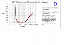
The bigger the output transformer corresponds generally to lower values of interstage coupling caps as one has to reduce the level of feedback at the lower LF end to avoid the phase response taking the circuit into oscillation. Hence the classic THD bathtub curve.
As I see it, the only proper way to predict the response of a Williamson design is to go through the physics and graphically plot what is actually going on...as per the old school of thought. As the feedback graph shows; the LF THD rise at the lower end is mainly the unobtrusive F2 and with it a reduced LS damping factor around any LS system resonance. This is the reason that many tube amps sound "fuller" at the LF end.
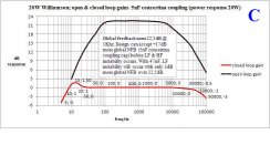
The "ills" of the Williamson can be ironed out as I have done with my 2 x 250Watt designs which can handle 15Hz at full power and offer excellent sounding with an optimum Q transient response. It can be done....My design route for Williamsons is by examining the closed gnfb loop transient response (very sim to PPL design of optimum Q/K for transient settling); by doing this the o/p tranny iron hysteresis BH loop transversal is automatically part of the complex algorithm. This avoids the guesswork.
richy
Attachments
Last edited:
Of ........... if it was done at low power ( say 1 watt ) the measurement was made, then the low frequency response will be even worse at high power./QUOTE]
On that theoretical measurement any manufacturer would have been "straight away" out of business.
richy
Of course it does not matter what the bandwidth actually is - unless you want identical performance. As for the Sowter transformer being measured at full power or not, if it was done at low power ( say 1 watt ) the measurement was made, then the low frequency response will be even worse at high power.
As for core size, halve the frequency and you double the core area.
In the case of a transformer having LOW DISTORTION one of the crucial factors is having a large core to reduce saturation.
Bandwidth of audio output transformers usually quoted at very low power (e.g. 1W) and full power, where lowest frequency should be 20Hz. At very low frequency lower limit is usually dependent upon measurement equipment and meaningful value. I think its possible to feed 1Hz@0.1W to 100W output transformer and get no roll-off, but does this really makes sense ??? IMHO, not at all, if not counting marketing of course.
Lowest frequency at full power must be 20Hz, anything below will make transformer too big and suffer from other side effects like leakage inductance and stray capacitance.
Partridge realized that in order to have a low distortion at 20 hertz, the core had to be capable of going some 10 times lower in frequency - hence 2 hertz was the roll off point.
Some pipe organs are capable of inaudible composite sub-bass sounds at low as 8.2 hertz and others at 16.4 hertz.
Partridge published his articles back in 1939, when quality of iron was abysmal compared to modern GOSS steel. For example, cores used by Partridge produced unbelievable 30% of 2nd order THD and about 18% of third order THD just at 10,000 Gauss (Partridge suggested to use air gap to reduce flux density and THD)! With today's materials you can go up to 15,000 Gauss with toroid core and get tiny fraction of a percent of THD.
Many people don't dig deep enough into details, an then building megaton air-gapped transformers rated at 5 - 10W only for no apparent reason.
One more thing - ultra-low frequencies like 8Hz usually filtered out during recording and mastering, because, when feed to loudspeaker drivers, they will cause nothing but high level of ugly intermodulation distortions.
Equally so, if - 20khz is the upper limit of the audio spectrum, the open loop bandwidth ideally should be 10 times higher ( 200khz ).
Not at all. Upper limit of audio transformer is determined by:
1) Leakage inductance, phase shift and NFB stability. Look at the articles in RCA book.
2) Resonant frequency, as product of leakage inductance and stray capacitance. Even if leakage inductance may be very low, and upper -3dB limit could be for example 200 KHz, resonant frequency may be much lower, e.g. 50 KHz only, due to many number of interleaved sections and as result, high capacitance.
Hello
to get a Patridge Williamson output transformers, built to their old specifications, would be nearly impossible. The used British Imperial lamination 28A (5" inch by 4 inch") is obsolete and the manufacturer for old Silcor 4 laminations (29 gauge) M.E.A doesn´t exist any longer. The later C-Core versions for this amplifier were made on HWR 50/32 C-Core, using a double chamber SRBP bobbin.
Even with the C-Core version for the Williamson Amplifier I have my doubts for reaching 200kHz with the NFB.
Best regards
Ingo
Partridge published his articles back in 1939, when quality of iron was abysmal compared to modern GOSS steel. For example, cores used by Partridge produced unbelievable 30% of 2nd order THD and about 18% of third order THD just at 10,000 Gauss (Partridge suggested to use air gap to reduce flux density and THD)! With today's materials you can go up to 15,000 Gauss with toroid core and get tiny fraction of a percent of THD.
Hello
Partridge is speaking in his article from current distortions and not from THD, these are two different things. You have to calculate the THD by multiplying the percentage from the current distortion with term of the effective Load (R) divided through the given Impendance (Zf) from the Transformer given at different frequencies.
Best regards
Ingo
I think its possible to feed 1Hz@0.1W to 100W output transformer and get no roll-off, but does this really makes sense ??? IMHO, not at all, if not counting marketing of course.
Lowest frequency at full power must be 20Hz, anything below will make transformer too big and suffer from other side effects like leakage inductance and stray capacitance.
It is exactly that 0.1W 1Hz bandwidth parameter I use to check transient loop response..i.e, the o/p stage working below saturation.
Also your lowest frequency idea of 20Hz needs to be lowered to 15Hz. I used 18 sections with counter-windings to neutralize the effect of leakage capacitance....result: a 11kg 200W o/p tranny lump (approx. 4x4.5x5.5" with M6) is capable of the 15Hz with 1.4% F2 using 20dB global nfb and a -3dB point at around 55Khz, using kelloggs paper between windings.
The sectionalized approach is described in the Radiotron Handbook with good detail.
The Physics:- Fourier analysis requires that if a good response is required up to 20Khz, then the bandwidth must be at least 60Khz, and at this figure the attenuation must not exceed 3dB. At this upper frequency, a leakage resonant frequency would have to be around 200Khz; with the secondary included in the feedback circuit.
There are some people around who claim that tampering with filters in the upper frequency i.e 50Khz, does influence the definition of the critical mid audio frequency range
A near approach would be a toroid, but to employ the same awkward interwinding techniques in the same way the ease of an EI core provides, that is provide several output sections and permutations, the work really begins. To design that superlative output transformer that everyone wishes- an open cheque book.
richy
Are you sure? It is not Fourier but someone else who says that as phase and amplitude responses are related by rational polynomials (assuming a minimum phase design e.g. no parallel paths) you can't get low phase changes (assuming this is what you mean by "good response") without an extended amplitude response. The issue then is whether your "good response" is actually a requirement - espcially as you have not distinguished between open and closed loop responses.richwalters said:The Physics:- Fourier analysis requires that if a good response is required up to 20Khz, then the bandwidth must be at least 60Khz, and at this figure the attenuation must not exceed 3dB.
Radiotron handbk 4th ed..Section 8 Fourier series page around 299. Midnight oil reading.
The nag is:-if the bandwidth of an amplifier is too narrow, i.e created by a poor quality o/p tranny stats; the 3rd harmonic of fundamental won't be reproduced enough, also effecting the also important F5, so the result is a squarewave resembling a skewered sine wave with increased THD. In practice, this exactly what happens. In all my reasoning assume global nfb is included. As we all should know at this stage, the phasing advance by the global nfb components, coupled with the loop gain available makes up for the transformer shortcomings til the amp loopgain runs out.
....especially when someone says "F3 isn't required, it's the one to rid off" ? but in the 1960's there were no true squarewaves in music, and the HF response was less, but now some transient digital sounds get pretty close, so the argument regarding wavefront risetime expressed in uS and the harmonics created does become relevant when high quality definition is required.
Trying to keep this simple for the layman-None of this is easy stuff to follow.
In designing the o/p transformers for my 250W Williamson, fortunately I had an old 200W Woden type of the 1950's exhibiting a staggering interwinding prim/sec capacitance of 5nF, and the screen/primary stats also reading high, as was each half primary resistances. Many amp builders could imply a those figures as poor HF extension ? Not implicitly, as a low impedance output stage can swell this. Many big power amps in the 1950's used sextets of 6L6's, so I copied the adage of parallel output stages.
The modern day transformer which I got Majestic (UK) to wind, comes out with a primary resistance 30% lower and the other interwinding specs between 20-30% lower than that 1950's equivalent.
So to those readers who maintain that a Williamson replica is impossible to make these days;...give it some thought.
richy
- Status
- This old topic is closed. If you want to reopen this topic, contact a moderator using the "Report Post" button.
- Home
- Amplifiers
- Tubes / Valves
- Who makes a Williamson output transformer ?