How much power are you wanting? With just a single 6AS7 in the output (i.e. one triode section for each of the upper and lower half of the output stage) you won't get very much. Remember that the output power you can achieve is principally limited by the current handling capacity of the output tubes, so this means that roughly speaking, the output power capacity grows as the square of the number of tubes. So you'd get a factor of four advantage in power by merely doubling the number of tubes. If you can get them for a few bucks apiece, why not go for it?
Chris
Chris
Take a look at this thread--
http://www.diyaudio.com/forums/tubes-valves/189282-vacuum-tube-otl-power-amp.html
Bottom of first page is the original scheme that evolved over the course of the thread.
The amp has been built by a few guys, some have modded it for fixed-bias, others have used a MOSFET/cap arrangement for auto-bias...
It can easily be used with different tubes to the 6C33C, Currently, I have 6KG6 (EL509) valves....
Worth a look anyway.
One Watt peak into 8 Ohms is the minimum target power. If I can easily get more than that I may go for it. I plan to try two parallel output tubes and see what it does(I'm not sure if I have more good 6AS7's than that anyway). I'd like to not go beyond 3 outputs per channel as it starts to get a bit outside my budget purchasing the output tubes beyond there. I'm actually using GP15M diodes in the current PS circuit I just could not remember the number when I drew the schematic and used what came to mind.
halfwave is not bad if good CLCL filter usedHmm--Looks like you drew your diodes in the PSU the wrong way round....
As Miles says--Half-wave is hideous, it will cause loads of hum and stress the caps and Tx in the PSU stages....
Easy to sort--Just use a full-wave bridge and alter the scheme accordingly...
There may be other issues with it--but those are the glaring obvious ones...
The heatercurrent of 2.5A pro tube p.x.So you'd get a factor of four advantage in power by merely doubling the number of tubes. If you can get them for a few bucks apiece, why not go for it?
Chris

Mona
Pardon my ignorance but what is a CLCL filter? I'm not too worried about heater current. I have a pair of OLD 6V PS chassis that each have three 6V secondary windings made up of wire thicker than some of the mains wires in the walls(!) which I can use for the final build....Maybe I should get a smaller 120V/6V transformer and connect it's 6v winding to the mammoth filament transformer I have and use it for an isolated 120V supply? I also am not responsible for paying the electric bill where I live so as long as those who are don't kick my but for this I'm good.
The heatercurrent of 2.5A pro tube p.x.
Mona
Well, I think one humble 6AS7 is perhaps being a little modest for an OTL. Two, perhaps, at least...?
Chris
I also am not responsible for paying the electric bill where I live so as long as those who are don't kick my but for this I'm good.
Well in that case, go for more tubes! And you'll have a nice heater for the winter months!
Chris
By the way, CLCL filter means smoothing capacitor after rectifier, then series inductor, then another smoothing capacitor, then another series inductor. I'd have expected another capacitor after that (CLCLC), because I wouldn't have thought you'd want a power supplier presenting itself as a source with the impedance of an inductor in series with it. But then I never use inductors, so what would I know?
I designed a low power OTL that doubles as a headphone amplifier + preamp. I have not built it yet.
I also am working on a design for a high power unit. My question is what driver do you recommend for lower distortion in the schematic?
My goal is to attain 80 watts from 6 6AS7 dual triodes. I sourced a place that has a bunch of them. They will probably sell them to me inexpensively.
The driver as it is produces about 80 watts into 8 ohms at about 0.75% distortion. I can lower it with in insane amount of feedback but I do not want to rely on feedback as an answer to distortion. Right now I have about 20dB of feedback to get the 0.75% number, way too much in my opinion.
Attachments
Well I finally got the revised version of my schematic built and producing an output after a day scratching my head as to why there was barely any measurable output....Long story short the output PS ground was not connected leaving a basically open circuit across the speaker terminals.
It seems to work well with two tubes, but with -80V to as high as -55V grid bias I can't get nearly as much output power as I did with my original circuit. From what I can tell the drive to the output tubes is hitting the rails at 17V peak. In the morning(it is about midnight here now) I plan to track down the stage(s) of the driver circuitry that are hitting the rails and then attempt to redesign/modify them to produce a greater maximum undistorted drive signal.
I figure that if I dial back the quiescent current to near zero(gotta keep some to avoid the crossover distortion of class B operation) and crank up the drive signal I should be able to run two or three outputs per channel with the same or better power than before and have low enough strain on the outputs for them to have a long service life.
I can lower it with in insane amount of feedback but I do not want to rely on feedback as an answer to distortion. Right now I have about 20dB of feedback to get the 0.75% number, way too much in my opinion.
20 db is small. as the baseline in futterman designs can be as high as 40 db NFB.
the 6as7 runs more linearly with less distortion when it is grid biased with some degeneration. there are two ways that this degeneration can be applied to this circuit. either NFB method or a constant current source ( like a mosfet or a power tube like a 6L6 in the anode).
since the output stage is approx .8 gain. your drive product should be 40 to 60 Vp-p max.
B+ of the driver stage should be double the output to achieve proper gain/drive slope ( i.e. 250V in drive stage and +/- 125V output).
In that case I'll try to increase driver stage B+ as a first step after isolating the stage hitting the rails. Last I checked the driver B+ was lower than 250V and the output rails were over 155V...
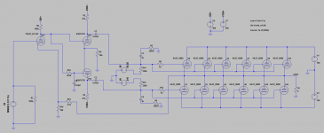
After wasting a few days trying(and failing) to get a working 6AS7 model in Multisim, so I could simulate the circuit before going to the effort to modify it, I've returned to working on it.
This time I think I have a good cheap reliable circuit that sounds as AWESOME as the first (output tube eating) version did. I bit the bullet and went with three parallel 6AS7's, and dropped the output rails to +/-60V. I'm getting 1.3Vrms@1KHz(max before driver goes into visible distortion) into an 8 Ohm power resistor(used as a dummy speaker load) which is about what my Heathkit A-7E's produce(they produce PLENTY of volume in my listening room and thus set the standard). There is 1.4VDC and .8VAC rms across R20 which I calculate is about 47mA DC+38mA AC PK or 85mA max current per each triode section(as long as I don't drive it to distortion) which leaves 40mA of headroom before hitting the 125mA max recommended current per section in the GE 6AS7 datasheet. If I'm correct the tubes should now be running conservatively enough to have a LONG service life.
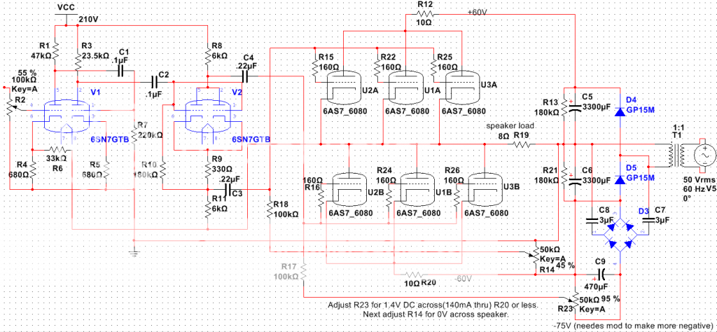
I initially tested it with 60mA per section, but dialed back the bias to 47mA per section without any reduction(that I could measure) in maximum undistorted output signal amplitude so I will try to reduce quiescent current further and see if I can without affecting output. I would have reduced Quiescent current further(if for nothing more than longer output tube service life) but the negative DC bias supply voltage is presently not negative enough to allow me to bias the current any lower. If I can run lower quiescent current with the same max output signal level I may try to get a higher undistorted drive signal for more output(via higher driver B+ or circuit changes).
Another idea I have is that since this will be a four channel(quadraphonic) amp and the majority of what I listen to is 2 channel(ie. stereo) that I'll create a mode switch to disconnect the rear output tubes from their speaker jacks, disconnect the phase splitter->output coupling caps from the rear channel phase splitters and connect those connections from the rear channels' output tubes to the corresponding points in the front channels, thus putting the output tubes for the rear channels in parallel with those of the front channels when in stereo mode. So the amp would be basically 3 outputs/channel in quadraphonic mode and 6 outputs/channel in stereo mode(so I should be able to rattle the windows in stereo mode if I want ).
If there are any errors in my schematic or math or if there are any relatively cheap/simple ideas to improve this design please let me know.
This time I think I have a good cheap reliable circuit that sounds as AWESOME as the first (output tube eating) version did. I bit the bullet and went with three parallel 6AS7's, and dropped the output rails to +/-60V. I'm getting 1.3Vrms@1KHz(max before driver goes into visible distortion) into an 8 Ohm power resistor(used as a dummy speaker load) which is about what my Heathkit A-7E's produce(they produce PLENTY of volume in my listening room and thus set the standard). There is 1.4VDC and .8VAC rms across R20 which I calculate is about 47mA DC+38mA AC PK or 85mA max current per each triode section(as long as I don't drive it to distortion) which leaves 40mA of headroom before hitting the 125mA max recommended current per section in the GE 6AS7 datasheet. If I'm correct the tubes should now be running conservatively enough to have a LONG service life.

I initially tested it with 60mA per section, but dialed back the bias to 47mA per section without any reduction(that I could measure) in maximum undistorted output signal amplitude so I will try to reduce quiescent current further and see if I can without affecting output. I would have reduced Quiescent current further(if for nothing more than longer output tube service life) but the negative DC bias supply voltage is presently not negative enough to allow me to bias the current any lower. If I can run lower quiescent current with the same max output signal level I may try to get a higher undistorted drive signal for more output(via higher driver B+ or circuit changes).
Another idea I have is that since this will be a four channel(quadraphonic) amp and the majority of what I listen to is 2 channel(ie. stereo) that I'll create a mode switch to disconnect the rear output tubes from their speaker jacks, disconnect the phase splitter->output coupling caps from the rear channel phase splitters and connect those connections from the rear channels' output tubes to the corresponding points in the front channels, thus putting the output tubes for the rear channels in parallel with those of the front channels when in stereo mode. So the amp would be basically 3 outputs/channel in quadraphonic mode and 6 outputs/channel in stereo mode(so I should be able to rattle the windows in stereo mode if I want
).If there are any errors in my schematic or math or if there are any relatively cheap/simple ideas to improve this design please let me know.
Last edited:
- Status
- This old topic is closed. If you want to reopen this topic, contact a moderator using the "Report Post" button.
- Home
- Amplifiers
- Tubes / Valves
- OTL design opinion