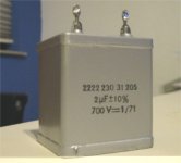
Learned an important lesson today. Did some rework on my PSU, and connected it all together again. The HT of the driver tube measured 200V right channel and 150V left channel (under load). Without load both channels measured the same. Very strange, it used to match very closely. After tripple checking everyting I found out that the first cap in the PSU was dead. It is a millspec 2uF/250V PIO, that now measures only 0.38nF on my DMM  Replacing the cap solved the problem.
The cap was rated 250V DC (75 deg) / 150V DC (85 deg), so it was simply underrated. It's a design flaw that never showed, till now. The reason I did the rework on my PSU is that it got too hot inside. Probably the cap died on a hot day when the PSU was getting very hot during testing. It gets 250V DC without load.
I'm very happy the thing didn't explode or shorten things....
Replacing the cap solved the problem.The cap was rated 250V DC (75 deg) / 150V DC (85 deg), so it was simply underrated. It's a design flaw that never showed, till now. The reason I did the rework on my PSU is that it got too hot inside. Probably the cap died on a hot day when the PSU was getting very hot during testing. It gets 250V DC without load.
I'm very happy the thing didn't explode or shorten things....
Attachments
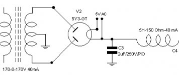
That C3 is a vulnerable position for any cap as it has to accept a massive peak voltage and considerable voltage swings. The oil/ paper versions used in older equipment (although bulky) were the best, although polypropylene or sim H.V types will work. Don't do as someone else did, fit an electroytic in this position. That is extremely dangerous practice.
rich
rich
Hi,
Not without equalising resistors and it'll still be a compromise and depending on equal Cs.
Cheers,
though if he connected 2 4uFs back to back it wouldn't kill the cap...get those long life 105deg ones...
Not without equalising resistors and it'll still be a compromise and depending on equal Cs.
Cheers,
Replaced the cap with this one. But I also use Philips Longlifes 105deg in the supply.
Inside the PSU
Inside the PSU
Attachments
Inside that incendiary box........the central / upper part of the photo.....that bit above the 10H 20mA choke........I can't quite make out the value of that series dual resistor chain on top of those caps ? It looks like 2.7R.......Yes /No ? My comp' monitor isn't the best for colour. Any more on the circuit ?
rich
rich
first prize 2R7 it is ...used in the 5687 12.6V heater supply.
Latest PSU
Latest Amp
Building pictures
pictures 1-45: prototype
55-100: first version of PSU
100-end : 2nd/current version of PSU.
Ralph
2R7 it is ...used in the 5687 12.6V heater supply.Latest PSU
Latest Amp
Building pictures
pictures 1-45: prototype
55-100: first version of PSU
100-end : 2nd/current version of PSU.
Ralph
- Status
- This old topic is closed. If you want to reopen this topic, contact a moderator using the "Report Post" button.
- Home
- Amplifiers
- Tubes / Valves
- Learned a lesson today