anyway, what is the reasoning for using solid state devices ?
Now there is a good question. Using a tube input stage and solid state output stage saves some money on output transformers and power supply chokes. You do have to be careful not to throw out the baby with the bath water by having the SS stage clip before the tube stage does. That will just give the worst of both worlds.
On the other hand, using a solid state input to drive a tube output will save money by using fewer tubes. The money can then saved to pay for the output transformer and power supply choke. Some say that the distortion in the output transformer is part of the magic valve sound and without it there is no point to any tubes in your amplifier.
Have I got it right or are there other considerations?
Last edited:
Have I got it right or are there other cosiderations?
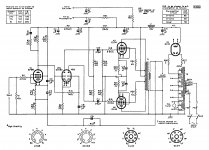
isolated small signal solid state input curcuit, converting single ended signal to balanced
A SS device for the Concertina/Cathodyne phase splitter makes good sense ( eliminates the filament to cathode breakdown issue, and increases the voltage swing available from a given B+, the high gm reduces the cathode follower distortion).
Composite (SS +tube) Darlington or Sziklai duals allow one to eliminate the OT (and eliminate the power tubes) while still having a tube-like clipping action. If you still want an OT in there, then use a 1:1 or 4:1 bifilar one with the composite drive setups for super feedback bandwidth thru the OT.
Composite (SS +tube) Darlington or Sziklai duals allow one to eliminate the OT (and eliminate the power tubes) while still having a tube-like clipping action. If you still want an OT in there, then use a 1:1 or 4:1 bifilar one with the composite drive setups for super feedback bandwidth thru the OT.
Bleed resistor across 0.7VBE doubles as a constant current source.
R4 in my drawing, keeps V1b's plate on a constant current loadline.
Its a freebie, so why the heck not take full advantage of it???
Also all filaments at ground potential, could run off one winding.
Another potential savings in cost and complexity.
R4 in my drawing, keeps V1b's plate on a constant current loadline.
Its a freebie, so why the heck not take full advantage of it???
Also all filaments at ground potential, could run off one winding.
Another potential savings in cost and complexity.
Last edited:
Driver tubes (or sand) only necessary if going into A2.
Even then, its only because the coupling caps essential to any
concertina will block DC and pump up a deep negative bias...
the MJ15035 is dissipating about 3.5 watts, the highest i have seen in a concertina if looking at historical circuits....
what if we bias a tube at those levels instead? like a 13FM7, small triode driving the big triode, i know that gain will be lower....
A SS device for the Concertina/Cathodyne phase splitter makes good sense ( eliminates the filament to cathode breakdown issue, and increases the voltage swing available from a given B+, the high gm reduces the cathode follower distortion).
So what we need is a FET 6SN7 on an octal base..

So we can substitute and use lower splitter/driver supplies and get higher OP.
Regards
M. Gregg
the MJ15035 is dissipating about 3.5 watts, the highest i have seen in a concertina if looking at historical circuits....
what if we bias a tube at those levels instead? like a 13FM7, small triode driving the big triode, i know that gain will be lower....
Thats cause I was foolishly trying to go into A2 without followers.
Power to do so is definitely there, but coupling caps won't allow.
Dissipation doesn't actually need to be so high with reasonable
values for R1,R2,R3. Since never going A2 for blocking anyway...
-----
As for drawing #28, "Like this?". No, and for exact same reason.
You want to drive A2 requires direct DC coupling from an emitter,
cathode, or source follower. Any scheme with AC cap coupling, no
matter how powerful, will only serve to pump up a blocking bias.
And if its not going into A2, and the open loop gain is sufficient,
and the driving impedance are equal without the plate loaded
differential stage (copy and paste from Williamson), then doesn't
need that driver pair or benefit from them in any way...
I got an extra +/- 50x Concertina Voltage gain out of the hybrid,
so its not wanting for gain, nor more current, nor for more power,
nor better balance. Its only caps I wish didn't have to be there...
Followers in see-saw paraphase might be an answer...
---
13MF7, I don't know it. But assume any triode must offers less
than B+/2 headroom? Not more than B+/3, I would think.
Sand continues to work at low voltages that starve any plate.
Beisdes, if not PNP or P-CH this topology is impossible anyway.
If we speak of regular cathodyne, then its just a cathodyne...
What feature are we comparing then, just quiescent current?
Last edited:
makes me think mosfet followers to directly couple to output tube grids
Yes sir! See Tubelab's PowerDrive.
Any scheme with AC cap coupling, no
matter how powerful, will only serve to pump up a blocking bias.
if I understand what you say, is basicly that a differential driver pair will never work well with blocking caps, but only makes sense when direct coupled
I guess that leaves the differential pair to only the very best amp builders
btw, is that one reason why PP tube amps are said to always be classAB ?
if I understand what you say, is basicly that a differential driver pair will never work well with blocking caps, but only makes sense when direct coupled
Not so. Take a LTP splitter, the Mullard 5-20 is as good as any, and insert the buffering FETs after the coupling capacitors. The followers are AC coupled to the splitter and DC coupled to the "finals".
Blocking distortion is eliminated and a positive grid current regime can be entered, should you so choose. Read what George Anderson (Tubelab) wrote. PowerDrive would allow you to take a Mullard circuit implementation using either 6L6s or KT88s into Class "AB2".Attachments
how do you reduce the standing current in the mj15035?
increase R2 and R3?
Yeah, just increase R2 and R3 equally to whatever you want...
But also, R1 must scale in 1/Mu proportion with R2's new value.
If you want Collector and Emitter impedances to remain equal.
VEmitter is divided by Mu when fed back through the Plate's field.
Therefore we must divide the Collector Voltage by Mu for feeding
back to the Cathode, to achieve the equal impedance effect.
R3 should properly equal R1+R2. if a low Mu triode were used,
that small fraction could become significant enough to matter.
Last edited:
If we just wanna split without voltage gain, and drive grid currents to AB2.
Maybe see-saw paraphased like R1=R2? Half baked, yet almost plausible...
Or the same thing upside down in P...
Or same thing rightside up, but M1 is maybe a Triode...
Maybe see-saw paraphased like R1=R2? Half baked, yet almost plausible...
Or the same thing upside down in P...
Or same thing rightside up, but M1 is maybe a Triode...
Attachments
Last edited:
Yes sir! See Tubelab's PowerDrive.
thanks, been looking at it after reading SY's posts about mosfet followers, i am giving it a try soon, and this circuit kenpeter posted may just complete the cast....
Yeah, just increase R2 and R3 equally to whatever you want...
But also, R1 must scale in 1/Mu proportion with R2's new value.
If you want Collector and Emitter impedances to remain equal.
VEmitter is divided by Mu when fed back through the Plate's field.
Therefore we must divide the Collector Voltage by Mu for feeding
back to the Cathode, to achieve the equal impedance effect.
R3 should properly equal R1+R2. if a low Mu triode were used,
that small fraction could become significant enough to matter.
got you...how is the power supply rejection for your circuit?
will it benefit from regulated supply?
- Status
- This old topic is closed. If you want to reopen this topic, contact a moderator using the "Report Post" button.
- Home
- Amplifiers
- Tubes / Valves
- SS phase splitters?