I have a hard time just figuring out what's connected and what's not on that schematic. Never mind what the inputs and outputs are. But here are my guesses:
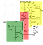
The top portion (marked in yellow) is a cap multiplier. Nice touch on the load resistor (30 kOhm) as emitter/source followers tend to go unstable if you forget those.
I think the optocoupler (red) is there to control the start-up and power-down behavior. Either that or it's used for on/off control. It's not an error amp - unless bang-bang/on-off control is used, which usually ends in tears. Optocouplers are rather nonlinear, hence, not that useful for linear control systems unless something is done to linearize them (been there, done that).
The circuit marked in green is a CCS. It sets up (10 + X) mA in the bottom resistor. X mA flows through the NPN and 10 mA through the two voltage regulator tubes. It's a bit of a hack in my opinion. I would have preferred a current mirror, but I guess it works well enough.
Those are my guesses. Perhaps Hpeter's point was to direct our attention to the components around the MOS device. That shows the diode trick that Pete Millett pointed out.
Unless I'm mistaken, this circuit still doesn't solve the fundamental issue with cap multipliers; that in order for them to work, they dissipate almost as much power as an actual regulator but with lower performance.
~Tom
Attachments
(volt.reg for screens)
when i read this thread, got a idea around gas voltage tubes; they require for best performance constant current.
they can have better voltage stability than Si diodes
this schema should do")
output voltage= Uvr+(Uzd-Ube) could be again tvo diodes in series
when i read this thread, got a idea around gas voltage tubes; they require for best performance constant current.
they can have better voltage stability than Si diodes
this schema should do
output voltage= Uvr+(Uzd-Ube) could be again tvo diodes in series
not only meant as screen supply
if ccs only used, when screen current changes also the gas stabilsator current changes.
they require minimum to work 5mA for example
idea on that schema is to provide constant current trough gas stabs, no matter what output 1mA or 1A ( tube alone)
if ccs only used, when screen current changes also the gas stabilsator current changes.
they require minimum to work 5mA for example
idea on that schema is to provide constant current trough gas stabs, no matter what output 1mA or 1A (
tube alone)- Status
- This old topic is closed. If you want to reopen this topic, contact a moderator using the "Report Post" button.