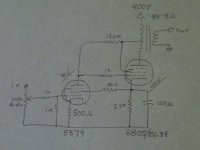
I've recently finished another variation on the direct coupled pentode amp with local feedback. For this version I stuck with the EL84 in the output position. I hadn't tried ultra-linear yet so I decided to use that for this amp. I found plate curves for the EL84 with 40% UL centered at 300v provided by Tom Schlangen. Using these curves I ran some sims using a straightedge and calculator.
At 300v and 40ma a load of 8kOhm looks like a good compromise for distortion and power yielding 3.4 watts with 3.6% D2 and .9% D3 before feedback is applied. The 40% partial feedback from the output tube should result in an output impedance around 300 Ohms. I had parts for a 400v power supply leaving 90v for the plate of the input tube.
In addition to the excellent distortion characteristics the ultra-linear connection eliminates the need for a regulated screen supply for the output tube. The E-linear design carries this simplification to the input stage B+ voltage. Direct coupling the input pentode allows the designer to feed the input screen from the cathode of the output tube.
I find the sound to be quite pleasant. My speakers are sensitive enough to rock on 3 watts. The sound is clean and detailed with good frequency extension.
Attachments
Good job Paul, thanks for sharing.
Will have more questions when I have a better grasp of ultra-linear and the like(currently studying the good stuff @ oestex.com)
Not yet smart enuff to see the feedback loop, can you explain or point me to some reading?
thanks in advance,
dennis h
Will have more questions when I have a better grasp of ultra-linear and the like(currently studying the good stuff @ oestex.com)
Not yet smart enuff to see the feedback loop, can you explain or point me to some reading?
thanks in advance,
dennis h
Tube Cad Journal put up an article on this kind of feedback. The Tube CAD Journal, partial feedback amplifier I had to read it a few times before I felt I understood it. Since the load of the input tube is attached to a tap on the transformer rather than to B+ a portion of the amplified signal from the output tube appears across it. The input tube must cause a much larger voltage swing across its load for the same output than would be needed without feedback. I found this a bit tough to grasp at first since the voltage at the plate of the input tube is the same with or without feedback.

- Status
- This old topic is closed. If you want to reopen this topic, contact a moderator using the "Report Post" button.