About two months ago I started to design and build an Single Ended Hybrid Amplifier .
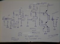
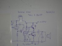
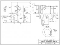
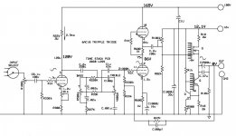
The circuit is simple , consists of one PCF802 tube ( two common cathode gain stages ) and two PL82 pentodes ( triode connected ) in SRPP configuration as driver and third stage in the same time , DC coupled to the output stage , which is an IGΒΤ power follower ( emitter follower onto current source ) .
The circuit runs at about 220V - 225Vdc for both the sands and the tubes , but with seperate power supplies .
The name "LUNATIC" was given because of the use of high voltage IGBT and the DC coupling between them and the tubes .
.
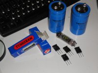
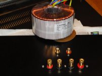
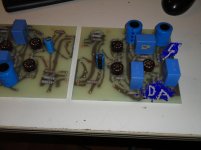
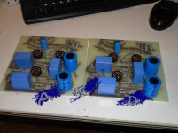
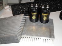
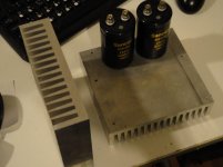
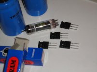
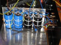
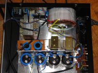
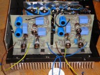
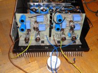
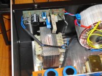
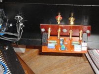
Here is some Fotos , the IGBTs , one PL82 and the output Capacitors ( in the first two fotos ) , heatsinks and power supply capacitors on the next two fotos , and finaly the two channels pcb and the 600VA power transformer for the output stage .
The circuit is simple , consists of one PCF802 tube ( two common cathode gain stages ) and two PL82 pentodes ( triode connected ) in SRPP configuration as driver and third stage in the same time , DC coupled to the output stage , which is an IGΒΤ power follower ( emitter follower onto current source ) .
The circuit runs at about 220V - 225Vdc for both the sands and the tubes , but with seperate power supplies .
The name "LUNATIC" was given because of the use of high voltage IGBT and the DC coupling between them and the tubes
.Here is some Fotos , the IGBTs , one PL82 and the output Capacitors ( in the first two fotos ) , heatsinks and power supply capacitors on the next two fotos , and finaly the two channels pcb and the 600VA power transformer for the output stage .
Attachments
Like any other SE class A amplifier it will have low Efficiency about 25% of the idle power , but this depends from other things too , like power supply , driver circuit , the load and the output elements too .
For the moment I have tested the tube circuit only ( the output is taken from the output of the SRPP via an capacitor 20μF/250V MKP and here is the results
Open loop : Input signal 1KHz 170mVp-p , output 74Vp-p onto 10KΩ load , this is a gain of about 53dB
with the same input signal I have 70Vp-p onto 5KΩ load
and the maximum undistorted signal at 5K load is 74Vp-p
Open Loop : -3dB point is at 48KHz .
Last edited:
My intention is to build an amplifier in Class A that would work better with high resistance speakers ( because I don't like high currents bias too much ) , like 16Ω loudspeakers , that's why I said it depends on the load ( meant loudspekers ) in the previous post , but I will tested with 8Ω loudspeakers too ( something like a tube OTL amplifier ) and so I choose B+ 220 volt for the IGBTs to be the same with the voltage of the tubes to DC coupled easy with them , I know it's a risk but I have a "plan B" if this fail , hehehe "plan B" it reminds me something here in my country ! , I said it's lunatic - crazy from the begining .
I will start with 80W to 100W idle for each channel and we will see , maybe there is a "little" chance to go in class A2 .
. I will start with 80W to 100W idle for each channel and we will see , maybe there is a "little" chance to go in class A2 .
Tssss .... , WHY?uh oh sand sound evil, and even the worst one .. igbt
Last edited:
if hexfets in audio are not optimal, what should i think about igbt?
does these switching animals have nice characteristics? I admit, i do not look in igbt datasheets though
One thing i dont like about endstage,is the one transistor is static-and second one does all the work. More symetric would be nice and eficient
does these switching animals have nice characteristics? I admit, i do not look in igbt datasheets though
One thing i dont like about endstage,is the one transistor is static-and second one does all the work. More symetric would be nice and eficient

An externally hosted image should be here but it was not working when we last tested it.
because i hate this when you have same polarity power transistors, you have to use before them pnp+npn
i wanted to avoid that

to have only igbt "sound", not also mixing in the bjt "sound"
igbt madness
not sure about this
top ccs can be made also from tube, then it will look almost like srpp
An externally hosted image should be here but it was not working when we last tested it.
not sure about this
top ccs can be made also from tube, then it will look almost like srpp
Last edited:
oops, error up there
An externally hosted image should be here but it was not working when we last tested it.
if hexfets in audio are not optimal, what should i think about igbt?
does these switching animals have nice characteristics? I admit, i do not look in igbt datasheets though
One thing i dont like about endstage,is the one transistor is static-and second one does all the work. More symetric would be nice and eficient
What is optimal for audio or not is a big story , that we can't cover it here ( it's a big debate ) , in my opinion most devices can play good if we treat them right , as for those IGBTs , their switching characteristics is very good they are new generation IGBTs , but here we have class A amp therefore we don't have to worry about those characteristics
, it will matter if we have class AB amp .Um... Isn't this the tubes forum? Since when did efficiency become the main objective?
The output stage is a class A emitter follower. Hence, one transistor does the "work" and the other acts as a constant current source. Seems pretty clean to me, actually.
~Tom
Very nice answer and gave me courage !! .
- Status
- This old topic is closed. If you want to reopen this topic, contact a moderator using the "Report Post" button.
- Home
- Amplifiers
- Tubes / Valves
- SE Hybrid Amp "The Lunatic one"