Hi guys!
I want to create the tube preamplifier or tube buffer under this schematic. If anyone has some schemes comments let go. Any help is welcomed.
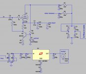
Just please tell me what is wrong what's wrong with this tube buffer (preamplifier)?.
Thank you for your cooperation!
I want to create the tube preamplifier or tube buffer under this schematic. If anyone has some schemes comments let go. Any help is welcomed.
Just please tell me what is wrong what's wrong with this tube buffer (preamplifier)?.
Thank you for your cooperation!
Attachments
Last edited:
I don't think this is going to work:
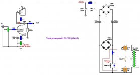
- With 60V B+ and a predetermined quiescent voltage of 40V, the 12AU7 will be biased at almost 0V. Positive swinging input signals will almost clip immediately.
- Taking the output from the anode makes for a high output impedance, with all kind of issues as a a result (attenuation, noise)
- Any impedance connected to the output will be in parallel with the 100k in the schematic. Assuming you have to drive impedances as low as 5k, you end up with 4k7. The frequency response with the 330nF cap will be high-passed at 102 Hz. With these values, you'de need at least a 1.7uF cap for a 20Hz response. You can play it safe with a 2.2uF or loose the 100k, so you'll end up with just the load impedance, and you can get away with 1,5uF.
- The cathode bypass cap is unnecessarily large. 22uF will probably do it.
- 300 ohms is not much of a grid stopper.
Edit: The 12au7 draws 150mA when the heater is connected in series. With that current, your 30Vrms transformer output will want to drop around 10,3 volts per resistor pair, leaving 9,4 volts for the heater. It's being starved. Consider a regulated DC heater supply at 12,6V for best performance.
Last edited:
What do you need it for ?
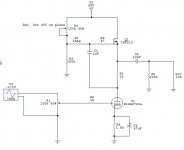
With a cap at the cathode + a ccs, you'll have a lot of gain with an 12au7. And since you don't have much voltage, that also means you will have to seriously limit the input levels. If you just need a buffer, you'll be much better served by a cathode follower.
Make your heater voltage negative and put a 3 to 4ma ccs in between your negative rail and the cathode and you don't even need an input cap. You'll be able to pass 2vrms into a 10K load with minimum distortion.
There might be a voltage surge at startup though (output cap has to charge and the voltage doubler is slow to rise). A relay with a simple delay circuit might be useful.
Attachments
Hi, 00940!
I want to connect the output CD player to the input audio amplifier with LM1875.
So this input resistance of the audio amplifier is about 33...47k (into a 33...47k load)
Led lamp with which to replace QTLP690C, because the ice is hard to be found?
ECC82 want to replace with ECC88JJ!?
Please provide changes to the schematic?
Thank you!
Last edited:
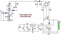
So, let's assume that your cdp output is about 1vrms (so 2.8Vp-p). Your lm1875 has max rails of 60V, probably more like 50V. With +/-25V rail, power into 8R is 20w, which means about 43Vp-p. 43/2.8 gives us a necessary gain of 15. The datasheet implementation of the lm1875 has a gain of 21. Ok, there should be no need for gain.
As for the ecc88, it won't work. First, your transformer is too weak for the 365ma required by the ecc88's heater. It's already a bit weak for the ecc82. Second, the ecc88 runs on a 6.3v heater. Even with a more powerful 15-0-15 xformer, that's a lot of voltage to burn from the 21vdc rails you get.
If you really want it to work with the ecc88, add a second transformer for the heater, something like a 9V/1A will do fine. If we have a second transformer, we can make things simpler, so let's get rid of the dual supply. The 470uf caps in the doubler must be at least 50V, preferably 63v, the 100uf must be 100V ones. the qtlp690c is just any red led (that's the only one by default in ltspice). The pot goes in front of the input cap. As said before, there is a thump at startup with such simple buffer, be careful not to blow your speakers, turn the preamp on before the amplifier or add a relay with a delay on the output.
Attachments
Hi 00940!
Can this red or blue LED diodes be used (replacement) for QTLP690C?
see datasheet: http://learn.adafruit.com/all-about-leds/the-led-datasheet
thanks!
Can this red or blue LED diodes be used (replacement) for QTLP690C?
see datasheet: http://learn.adafruit.com/all-about-leds/the-led-datasheet
thanks!
Last edited:
maybe framegrid more appropriate?
If you are able attach a schematic.
thank you
B+=150V ??
All right, I was wrong and understood.
Or, what to change of the schematic if we increase the anodic voltage on the B+=150V ?
(see back schematic of 00940)
thanks and cheers!
sorry i meant framegrid tubes, ecc88 or better
lower internal resistance (2k5), higher steepness. should work better at low voltages than 12au7
All right, I was wrong and understood.
Or, what to change of the schematic if we increase the anodic voltage on the B+=150V ?
(see back schematic of 00940)
thanks and cheers!
Last edited:
Yet another Ripped off design - this time it is the Cavalli Headwize SOHA.
Be more specific!?
Yes, see the web:http://forum.diyaudiotr.com/onyukseltec-tonkontrol/tube-preampli-class-uzerine-t780-10.html
So let's go with this latest schematic proposed by 00940.
cheers!
Last edited:
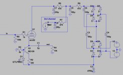
Just use any cheap red led you can get your hand on and adapt the value of the CCS resistor (R2 in my last schematic) to get in between 5 and 8 ma. To get that value remove the base to emitter voltage (usually about 0.65v) from the transistor from the forward voltage of the chosen led (usually about 1.8v for a red led) and divide this value by the chosen current. So, for example, (1.8-0.65)/0.007= 165.Hi 00940!
Can this red or blue LED diodes be used (replacement) for QTLP690C?
Or you can use a string of 3 1n4148 diodes instead of the led. Forward voltage at 5ma is 0.6V on those so 3 in serie will give you 1.8v.
Increasing the B+ won't change much in my last proposition considering the signals involved. It would allow maybe some regulation of B+. However, with a B+ of 150V, we have a lot more options, especially if we can use more tubes. It really boils down to how much you want to spend, what parts you already have on hand, what you really want from this preamp (you don't "need" gain but maybe you "want" some) and so on.
What are these 165 (1.8 / 065 = 165)?
Otherwise the buffer I want to use between Tecnics CD player and amplifier with LM1875.
This amplifier with LM1875 operates with power supply UCC =+ /-22V and speakers load 30V/8ohm (Gain 22x "22k/1k")
Thank you for your cooperation m-r 00940.
cheers!
Otherwise the buffer I want to use between Tecnics CD player and amplifier with LM1875.
This amplifier with LM1875 operates with power supply UCC =+ /-22V and speakers load 30V/8ohm (Gain 22x "22k/1k")
Thank you for your cooperation m-r 00940.
cheers!
What are these 165 (1.8 / 065 = 165)?
Otherwise the buffer I want to use between Tecnics CD player and amplifier with LM1875.
This amplifier with LM1875 operates with power supply UCC =+ /-22V and speakers load 30V/8ohm (Gain 22x "22k/1k")
Thank you for your cooperation m-r 00940.
cheers!
So that in this case R2 = 165R (R=ohm) and current 7mA!
Last edited:
- Status
- This old topic is closed. If you want to reopen this topic, contact a moderator using the "Report Post" button.
- Home
- Amplifiers
- Tubes / Valves
- "Diamond" tube preamp with 12au7