I'm posting this thread to help out another member (Ranhaber) building a Tubelab SE.
He is in 220V land and has a James 9612 power transformer with 230V primaries, and his secondary voltages are measuring low even with the transformer unloaded.
The 9612 has lots of 5V and 6.3 volt taps, and I've suggested that he can boost the secondary voltages by using one of the spare 6.3V taps in series with the primary winding, or perhaps both a spare 5V and 6.3V winding for even more volts.
Is this the best approach and is it safe? I realize that some isolation is sacrificed doing this; is there a better way?
All of the gory details are in this thread starting at post #58:
http://www.diyaudio.com/forums/tubelab/218283-tubelab-se-2.html
Remember, boosting the primary increases the voltages observed at all secondaries used "normally".
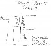
If this is an accurate description of the James' secondary situation, configure S4 and S5 for 5 V, phase them up, and wire them in series. Use that composite to boost the primary.
Regulation effects will probably lead to a boost slightly greater than 10 V., but that's the best that can be done, without acquiring additional "iron".
Attachments
Remember, boosting the primary increases the voltages observed at all secondaries used "normally".
Thanks Eli! He needs to raise all of the secondary voltages.
So, what you are saying is use two 5V windings in series and put these in series with the primary........If the phasing is correct we get a 10V boost multiplied to the secondary. If one of the 5V is flipped we will get zero boost I would assume, since they would cancel.
No worries about isolation?
There is highly likely to be an isolation problem with using a secondary winding on the primary due to the safety related insulation and creepage/clearance design of the transformer. The safety issue could only be clarified by a design inspection, which if you weren't in contact with the designer could involve a tear-down. Some transformers even have a safety earth screen that physically separates all primaries from all secondaries, whereas others use separate winding sections with double-insulated safety rating that don't per se need a protective earth.
There is highly likely to be an isolation problem with using a secondary winding on the primary due to the safety related insulation and creepage/clearance design of the transformer.
I can't argue with those remarks. The 100% safe way to boost that James primary is with a separate 10 VAC "chunk of iron". A Hammond 266L20 will get the job done.
I can't argue with those remarks. The 100% safe way to boost that James primary is with a separate 10 VAC "chunk of iron". A Hammond 266L20 will get the job done.
Agreed. But to avoid the possible saturation issues referred to (when using the boost configuration), put the buck or boost winding from the additional transformer in series with the secondary of the main HT power transformer. That way the HT transformer is known to be running within its design parameters.
Agreed. But to avoid the possible saturation issues referred to (when using the boost configuration), put the buck or boost winding from the additional transformer in series with the secondary of the main HT power transformer. That way the HT transformer is known to be running within its design parameters.
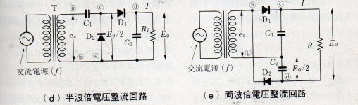
Boosting the rectifier winding is fine, when bridge rectifiers and "full wave" doublers are employed. Unfortunately, the James power trafo in question is configured for FWCT rectification. Boosting the primary is the simple option. Also, the filament windings are reading low. Once again, boosting the primary is the way to go.
To avoid saturation, the builder will have derate the VA number of that James "chunk of iron". Not using S4 and S5 should get the job done.
I'm posting this thread to help out another member (Ranhaber) building a Tubelab SE.
He is in 220V land and has a James 9612 power transformer with 230V primaries, and his secondary voltages are measuring low even with the transformer unloaded.
The 9612 has lots of 5V and 6.3 volt taps, and I've suggested that he can boost the secondary voltages by using one of the spare 6.3V taps in series with the primary winding, or perhaps both a spare 5V and 6.3V winding for even more volts.
Is this the best approach and is it safe? I realize that some isolation is sacrificed doing this; is there a better way?
All of the gory details are in this thread starting at post #58:
http://www.diyaudio.com/forums/tubelab/218283-tubelab-se-2.html
i am really scared even to try bucking or boosting at the primary side, i have done it at the secondary side, i will do it anytime it needed to be done...
")
Hi,
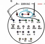
I tried to boost the primery like in the picture below.
For a second i mesured the same 4.5V and 6V (expected 5V and 6.3V) as in normal connection, and then 0V for all.
The taps i mesured were the bottom ones (4A each).
I pulled down the voltage and that's it. (my girlfriend insisting that i go to bed)
p.s. the fuse looked ok.
Attachments
Hi!
voltage doublers work best in low to medium current power supplies. For a heater supply you would need rather large caps. Doable, but keep in mind that the current load on the transformer secondary doubles when it works into a voltage doubler circuit.
Best regards
Thomas
voltage doublers work best in low to medium current power supplies. For a heater supply you would need rather large caps. Doable, but keep in mind that the current load on the transformer secondary doubles when it works into a voltage doubler circuit.
Best regards
Thomas
I second that.Hi!
voltage doublers work best in low to medium current power supplies. For a heater supply you would need rather large caps. Doable, but keep in mind that the current load on the transformer secondary doubles when it works into a voltage doubler circuit.
Best regards
Thomas
I would not advise that approach, even if it is doable to some degree.
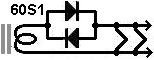
What about using a pair of ordinary high-current silicon diodes, that will be added to the heater chain to drop the heater voltage by about 0.7V. Like the picture below.
i mesured 6.1V unloaded. so will it be good for 5V heater rectifier?
i mesured 6.1V unloaded. so will it be good for 5V heater rectifier?
Attachments
Last edited:
Hi!
Agreed! The heater winding might heat up a lot due to the current spikes.
Better get a proper power transformer for the task
Thomas
I would not advise that approach, even if it is doable to some degree.
Agreed! The heater winding might heat up a lot due to the current spikes.
Better get a proper power transformer for the task
Thomas
Hi!
Those diodes will dissipate the same amount of heat as properly sized resistors for the task. No big advantage. With resistors you can better fine tune the voltage to the required level.
Thomas
What about using a pair of ordinary high-current silicon diodes, that will be added to the heater chain to drop the heater voltage by about 0.7V. Like the picture below.
Those diodes will dissipate the same amount of heat as properly sized resistors for the task. No big advantage. With resistors you can better fine tune the voltage to the required level.
Thomas
In my opinion:What about using a pair of ordinary high-current silicon diodes, that will be added to the heater chain to drop the heater voltage by about 0.7V. Like the picture below.
i mesured 6.1V unloaded. so will it be good for 5V heater rectifier?
1) Diodes are better when the load varies a lot. This means a (semi)constant voltage drop. But, as already mentioned, you can't easily tune the voltage.
2) Resistors are better when the load is constant. You can more easily tune the voltage drop and the constant drop of a diode isn't needed. In addition, the resistor helps with inrush current.
In both cases roughly the same power is dissipated. (It's actually slightly less in the diode, but I'll skip the math here. The difference isn't relevant.)
For a tube filament, number two applies. I'd use the resistor if given the choice between resistor and diode.
Given the local supply voltage and the 230V primary I would expect the secondary voltages to no more than 5% low under load. I'm wondering about the accuracy of the voltmeter used to make these measurements.
I am not a fan of boost/buck winding connection when secondaries are used to do it for safety reasons. A small 9V - 12V filament transformer configured as an auto-transformer on the primary side of the transformer is a lot safer and IMLE works very well. (Also leaves those filament windings available for possible use.)
I am not a fan of boost/buck winding connection when secondaries are used to do it for safety reasons. A small 9V - 12V filament transformer configured as an auto-transformer on the primary side of the transformer is a lot safer and IMLE works very well. (Also leaves those filament windings available for possible use.)
after a good night's sleep......
Ranhaber: A comment and an idea......
In your configuration in post #10 since you are using two windings in series with the primary you need to have all of the windings in the proper phase. If one (or both) of the LV windings are bucking instead of boosting, your voltages will be lower, or only slightly raised.
Try it with one of the 6.3V windings to start, and convince yourself that you can boost/buck, then add the second winding.
Here is another idea that may be a lot more practical and eliminates the isolation and saturation issues, and may even offer some improvement for a Tubelab SE:
Don't boost anything; use the transformer as-is. This gets you 350-0-350 or so which is more than enough for 300B operation.
Use a 6.3V winding with a dropping resistor for the rectifier. (Experts: Is this practical?)......or diodes using the forward voltage drop?
Use two 5V windings in series for around 9V into the filament regulator. This provides additional voltage headroom into the filament regulator which may be a good thing. The Tubelab SE regulator has minimal regulation with 6.3V input. This higher voltage will burn more heat; you'll need ample heat-sinking.......We'll have to look at the specs for the regulator to verify.
For those following along, here is the schematic:
Schematic
Last edited:
I'm wondering about the accuracy of the voltmeter used to make these measurements.
I'm wondering that too.........perhaps a CAREFUL measurement of the house voltage at the wall...
- Status
- This old topic is closed. If you want to reopen this topic, contact a moderator using the "Report Post" button.
- Home
- Amplifiers
- Tubes / Valves
- Bucking and boosting a tube power transformer