Disclaimer 1: I'm posting this in the tubes forum because I doubt it would receive much attention in the headphones forum (seems mostly ss over there). Sorry if it was a mistake.
Disclaimer 2: it involves opamps, don't me.
me.
This said, I once had a nice headphones amplifier which made use of the following topology:
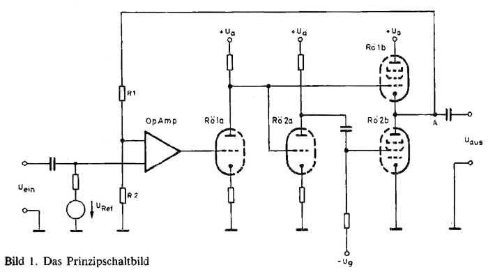
It was a kit by Helmut Becker from Audiovalve (see details here: PCL805-Roehren-Kopfhoererverstaerker_von_Helmut_Becker).
Of course, I could just clone it, I've got all the information needed. But it was in fact more powerful than needed (especially for the hd650 I've got now) and I was wondering if a simpler version couldn't be made, using ecl84 rather than ecl85.
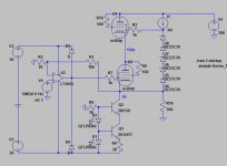
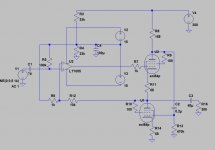
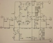
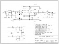
Here are two ideas (see attached pics). They are determined by what I've got on hand (a good 300Vdc supply, a quad of ecl84) and the schematics are just concepts (lacking dc protection and the like).
The first one uses three supply (-20/+20/+300), is dc-coupled (which is stupid... output caps might be safer) and uses a cascoded cathode follower inside the opamp feedback loop. About 25ma standing current.
The second one uses a White cathode follower output inside an opamp feedback loop. Which means input and output caps and a floating PS for the opamp. Same standing current but can deliver a lot more current into the load.
Any of these looking like a worthwhile summer project ?
Disclaimer 2: it involves opamps, don't
me.This said, I once had a nice headphones amplifier which made use of the following topology:
It was a kit by Helmut Becker from Audiovalve (see details here: PCL805-Roehren-Kopfhoererverstaerker_von_Helmut_Becker).
Of course, I could just clone it, I've got all the information needed. But it was in fact more powerful than needed (especially for the hd650 I've got now) and I was wondering if a simpler version couldn't be made, using ecl84 rather than ecl85.
Here are two ideas (see attached pics). They are determined by what I've got on hand (a good 300Vdc supply, a quad of ecl84) and the schematics are just concepts (lacking dc protection and the like).
The first one uses three supply (-20/+20/+300), is dc-coupled (which is stupid... output caps might be safer) and uses a cascoded cathode follower inside the opamp feedback loop. About 25ma standing current.
The second one uses a White cathode follower output inside an opamp feedback loop. Which means input and output caps and a floating PS for the opamp. Same standing current but can deliver a lot more current into the load.
Any of these looking like a worthwhile summer project ?
Attachments
Neat little circuit. Reminds me of the Borbely hybrid opamp (scrolling down to fig 4: Designing An Opamp Headphone Amplifier | HeadWize ). But more economical by using the heaters as load.
This said, I already have a tube+sand hybrid: 12au7 gain stage on 150v, ccs loaded, followed by a servoed darlington buffer. Sounds nice but I'd rather do something different.
This said, I already have a tube+sand hybrid: 12au7 gain stage on 150v, ccs loaded, followed by a servoed darlington buffer. Sounds nice but I'd rather do something different.
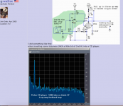
I did something like this:
when inserting some tubyness (AKA a little bit of 2nd H) into a CD player.
More such at Modifying CD player DAC circuits
An externally hosted image should be here but it was not working when we last tested it.
when inserting some tubyness (AKA a little bit of 2nd H) into a CD player.
An externally hosted image should be here but it was not working when we last tested it.
More such at Modifying CD player DAC circuits
Ever since the original article was published in the German ELRAD magazine in 1984, I've always been scratching my head why one would need an output power of about 5 watts into his 600 ohms headphones  …
…
Nevertheless, Helmut Becker/Audiovalve appeared to be quite successful in marketing this amplifier as a complete built as well as a construction kit in those days.
Best regards!
…Nevertheless, Helmut Becker/Audiovalve appeared to be quite successful in marketing this amplifier as a complete built as well as a construction kit in those days.
Best regards!
It is absolutely insane. 5W on 600 Ohm would only decrease S/N ratio and make microphonics of tubes more audible. I've found that 5W on 32 Ohm output would drive any available planar magnetic cans.
Wavebourn - Headphone amp driving speakets | Facebook
Wavebourn - Headphone amp driving speakets | Facebook
Should have made clear I was asking about the valve placement in feedback loop.wa2ise put it in the loop return to +input. It's of course in current mode. The opamp output is *the* output. I've been using a CF output ( fb loop) and buffering with another stage. Two very different ways of using tube in fb loop.
And other question is about the 47k, is it really working?
The power level not an issue for me.
And other question is about the 47k, is it really working?
The power level not an issue for me.
Attachments


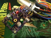
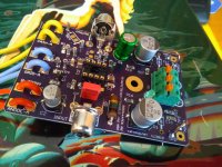
Test board stuffed and tested, going to try a nlr non-linear resistor. I have some, not mov or varistor or log semi diode etc. The non linearity is sort of programmable using dc bias.
A better name would be asymmetrical resistor. NLR sounds like non linear but symmetrical. If it looks promising going to add a .1" sip for potted device.
A better name would be asymmetrical resistor. NLR sounds like non linear but symmetrical. If it looks promising going to add a .1" sip for potted device.
Attachments
Last edited:
A vacuum tube in an NFB loop will give you the *opposite* result of what you are seeking, since the Op Amp will try HARD to compensate for it, so if you want to add "tubyness" it´s not the way.
I first found that, repairing Guitar oriented Ada Microtube Guitar amplifiers: basically a normal SS power amp (there were Bipolar versions, this one, and ADA Micro Fet , with MosFet outputs) which included a 12AX7 half inside the loop.
I was baffled because when I found the output clipped like a regular SS amp, flat top and all, I scoped tube plate to find what it was actually contributing and to my amazement found a "tit" or "nipple" shaped waveform instead of the smoothly rounded one I expected. WTF?
Until I realized that NFB tried to compensate for power transistor nonlinearity (which was starting to clip) and applied exact opposite error correcting signal.
Basic NFB behaviour.
IF you want tubyness, best is to use tube "raw", no correction applied, so you let it display all its glorious "flaws" ... and then faithfully amplify that.
A vacuum tube in an NFB loop will give you the *opposite* result of what you are seeking, since the Op Amp will try HARD to compensate for it, so if you want to add "tubyness" it´s not the way.
I first found that, repairing Guitar oriented Ada Microtube Guitar amplifiers: basically a normal SS power amp (there were Bipolar versions, this one, and ADA Micro Fet , with MosFet outputs) which included a 12AX7 half inside the loop.
I was baffled because when I found the output clipped like a regular SS amp, flat top and all, I scoped tube plate to find what it was actually contributing and to my amazement found a "tit" or "nipple" shaped waveform instead of the smoothly rounded one I expected. WTF?
Until I realized that NFB tried to compensate for power transistor nonlinearity (which was starting to clip) and applied exact opposite error correcting signal.
Basic NFB behaviour.
IF you want tubyness, best is to use tube "raw", no correction applied, so you let it display all its glorious "flaws" ... and then faithfully amplify that.
That must have been your Eureka! moment! But yes you are absolutely right, including the tit on the anode voltage.
Jan
In looking at many op-amps , above 5vac out third and fifth harmonic visible then at 6-7vac they are extremely high. That must be why the op-amp line outs from 90s never exceeded specify 5vac. But I've already taken it into consideration with a simple compressor. So the tit never shows. From 0-5vac can't see second,third or fifth. 130db range.
Low cost sound cards often internally run on single 5V supply, which means absolutely max undistorted output about 4V pk-pk which is 1.4Vrms.
Some better units have an internal switching -5V supply generator which means they can handle double the signal. Still, easy to internally clip the soundcard.
Jan
Some better units have an internal switching -5V supply generator which means they can handle double the signal. Still, easy to internally clip the soundcard.
Jan
- Status
- This old topic is closed. If you want to reopen this topic, contact a moderator using the "Report Post" button.
- Home
- Amplifiers
- Tubes / Valves
- Tubes in an opamp feedback loop?