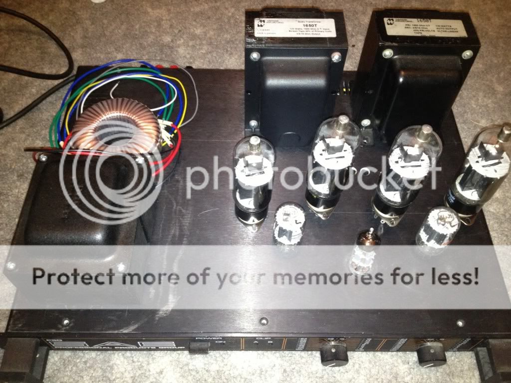
Back on topic, I am looking at the Hammind 1650T which is 1.9K primary and rated at 120W.
Maybe a quad of 6CB5s per channel would work better into 1.9K?
What screen voltage would be optimal for this arrangement? Do you select the screen voltage based on the anode load?
I am considering using a doubler for ~650-700V B+. I have some spare 180V transformers that I can use for the screen supply depending on the screen current demand. Maybe a choke type input for ~162v on the screens?
Or is my original plan to use a lower B+ better?
Thanks!
Nice looking OBs!.........They are fully passive and dynamic as almost any box speaker I've heard. The bass drivers are Acoustic Elegance IB15, midrange Peerless 830883, and the BG Neo3PDR with back cup removed for the tweeter.
I use these mounted in a pair of 1941 vintage Zenith console radios.
Silver Iris OB 15 Coaxial Unit [SI-OB-15] - $175.00 : Zen Cart!, The Art of E-commerce
The big difference is the efficiency. My speakers are about 96db. They will work with a 2 WPC 45 based DHT SET, but you can't play loud bass heavy music. Feeding them with a 15 WPC triode wired KT88 SET allows Pink Floyd and Depeche Mode, and the bass can be heard inside the house across the street.
I have fed these things with all sorts of amps, SE tube, P-P tube, a 100 watt Marshall, and even a little 15 WPC class D chip amp, but the absolute killer for bass transients and "rock concert in the living room" realism is a 125 WPC sweep tube amp based on Pete Millett's big red board. This amp used 6HJ5's with a 3300 ohm load and 600 to 625 volts of B+, conventional G1 drive class AB1.
The term "effortless" best describes the system since there is about 20 db of headroom at loud listening levels where the average power is about 1 WPC. Big bass transients don't even slow the amp down. It has been operational for over 2 years and at least a dozen clones have been made.
This has prompted me to design a new amp, but time has been very sparse lately. It is still in the early breadboard stages.
What screen voltage would be optimal for this arrangement? Do you select the screen voltage based on the anode load?
I have built a lab setup with variable power supplies for just about every voltage in an amp. I have a two sets of OPT's that allow me to test at 1250, 2500, 3300, 5000, 6600, and 13200 ohms. Impedances in between these values can be tested by using a load resistor different than 8 ohms. I have a big collection of 100 and 250 watt Dales, and a pair of 500 watt 8 ohm loads.
I simply wire up a set of tubes and turn knobs to find the optimum trade off between power, distortion, harmonic distribution, and efficiency. Maybe this is a bit emperical for a true engineer, but it has been working for me for far longer than I have had an engineering degree! Whazza load line??????
I have found that almost all sweep tubes behave the same as long as the tube in question has the peak cathode current capability to slam those 15 inch cones around with the same authority that the hammer puts into the bass drum head, AND the plate dissipation capability to avoid meltdown at your chosen power level.
Watch the idle dissipation at high B+ voltages too. 40 mA at 650 volts is 26 watts! I run my 24 watt tubes at 30 mA on 630 volts for 19 watts. This is where the low idle current of screen drive shines.
Just about every true horizontal sweep tube (not the early tubes based on conventional audio tubes like the 6BG6) will be happy with 150 volts on the screen. Trying to hang too low of a load impedance on a small tube (below 2K ohms on a 13GB5 comes to mind) can require a bit more voltage like 175 volts. The screen grid on a sweep tube needs to be fed from a regulated supply, so design your regulator to cover 150 to 175 volts and you have it covered. The regulator doesn't need to be a uber regulated feedback system with .001 ohms output impedance, a VR tube or zener string and a mosfet or cathode follower is fine.
Tube dissipation capability requirements can be figured by knowing the maximum power output level, and the plate efficiency in the output tubes. The plate efficiency can be determined by testing. You measure the output power, the plate current in each tube and the plate voltage.
A typical G1 driven class AB1 sweep tube amp can achieve 65% plate efficiency at just below clipping, if it sees an optimum load impedance. This means a 100 watt amp will consume 154 watts of DC from the power supply to make those 100 watts of audio. This burns 27 watts in each output tube, which is just above the 6CB5 spec, but you aren't going to listen to a continuous tone at 100 watts. I have found that any of the 25 watt class sweep tubes live well in 125 WPC amps. I use 6HJ5's which are rated for 24 watts.
The peak current capability requirements can be estimated by looking at the impedance curve of your loudspeakers and the ratio of your OPT, and the B+ voltage. We assume that a sweep tube can pull its plate down to near zero. It can in screen drive, possibly blowing the screen grid, and it can get to 30 volts or so in G1 AB1. So if your speakers are exactly 8 ohms for all frequencies and dynamic conditions (NOT!), a 3300 ohm OPT will draw 727 mA from 600 volts. 600 volts / 825 ohms = 727mA. The max peak current for a 6CB5A is 850 mA. This limit will be reached when you speakers go below 6.8 ohms with a 3300 ohm OPT on 600 volts.
These numbers assume that the amp is driven to the edge of clipping at the moment of the transient. Attempting to push the amp harder will not cause overcurrent, just distortion since the amp will clip.
Reducing the load impedance below 6.8 ohms AT FULL POWER will cause over current, but you will be clipping and distortion should be audible. Operating the amp where no audible distortion is present will prevent overcurrent failure. Use bigger tubes when building a tube guitar amp.....or select speakers with a resonance peak just below 80 Hz and you won't blow anything!
The manufacturers usually publish an impedance VS frequency curve for loudspeakers. It is generated under static single frequency tone test conditions. This curve does not cover dynamic conditions where the cone could be moving in one direction and a dynamic transient instantly tries to reverse its direction. My attempts to measure this have been futile, but I believe my old Yamaha NS-10MS monitors can go below 4 ohms where the published curves show values from 8 to 25 ohms.
I believe that the peak current capabilities of a sweep tube are responsible for its dynamic capabilities. The 6CB5A is an old design with 825 mA ratings. There are sweep tubes with 1400 mA peak current ratings. Compare that to a 6L6GC with 400 mA ratings.
Since summer is over, my kids are back in daycare, and winter is coming up, I decided today to resurrect this project. I tried to sell the output iron, but to no avail.
If I use a separate power transformer for screens, does it need regulation, or just good filtering?
Thanks!
If I use a separate power transformer for screens, does it need regulation, or just good filtering?
Thanks!
Hi,
Yes, I did want to build the amp like that. I ran into space issues. If it were a UL circuit with KT or EL tubes, I would have just gone with it.
Is Zener string regulation sufficient? The reason I restarted this project is that I have about 95% of the parts including spare tubes. This chassis is also trimmed out with all the hardware, pots to control level, etc. along with being pretty large to help play around with layout.
I went with the 6GF7 as a concertina type phase inverter per my schematic a few posts back. Then just used a single 6DJ8 as the VA. Hopefully I can get enough swing out of the front end to get some decent power. I plan to knock out holes today and mount the parts. I'm not going for pretty here")
Yes, I did want to build the amp like that. I ran into space issues. If it were a UL circuit with KT or EL tubes, I would have just gone with it.
Is Zener string regulation sufficient? The reason I restarted this project is that I have about 95% of the parts including spare tubes. This chassis is also trimmed out with all the hardware, pots to control level, etc. along with being pretty large to help play around with layout.
I went with the 6GF7 as a concertina type phase inverter per my schematic a few posts back. Then just used a single 6DJ8 as the VA. Hopefully I can get enough swing out of the front end to get some decent power. I plan to knock out holes today and mount the parts. I'm not going for pretty here
I got the chassis fully cut and the filaments wired up. Pulled it up on my variac to make sure I did not short anything with the heavy gauge wire. With just a bridge (no cap), I see about 310VDC. I think I may need to go with a doubler to get a B+ high enough to make any decent power. I fear that, after filtering, and a load is placed on the secondary, the B+ will be below 300V and decent power will be unobtainable.
Thoughts?
Thoughts?
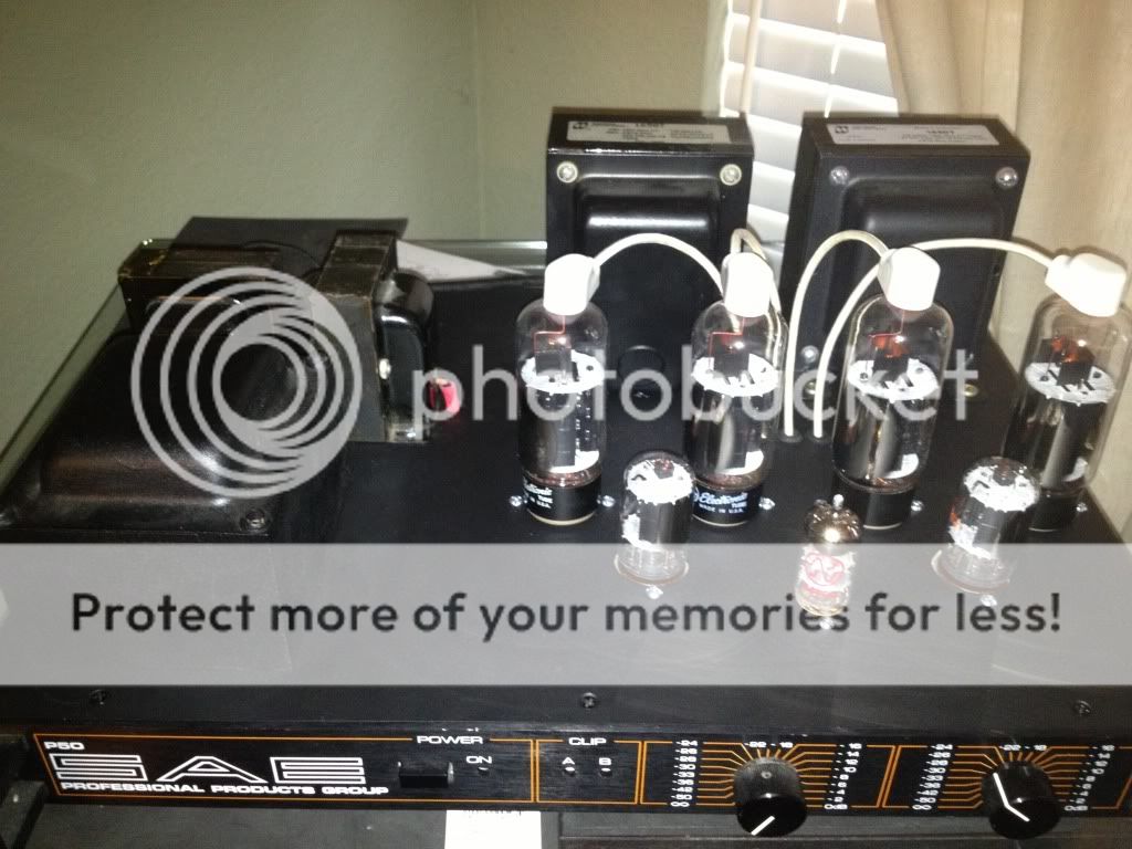
I got my PS wired up today. Here is what I built:
For some reason, if I clip the Zener out, it is fine resulting in a B+(unloaded) of around 355V. With the Zener in place, I can crank the variac up to about 200V before it acts like a dead short. Any reason for this? I loaded it with a 470K resistor I had paying around, but I got the same results.
Thanks!
An externally hosted image should be here but it was not working when we last tested it.
For some reason, if I clip the Zener out, it is fine resulting in a B+(unloaded) of around 355V. With the Zener in place, I can crank the variac up to about 200V before it acts like a dead short. Any reason for this? I loaded it with a 470K resistor I had paying around, but I got the same results.
Thanks!
There is a lot of energy stored in those capacitors. On power up they will charge until the voltage reaches the zeners conduction point. Once the zener begins to conduct it's internal temperature will rise causing its zener potential to drop causing more current to flow from the capacitors into the zener, causing more internal heating. Within a few milliseconds the zener fries to a short....poof, dead.....
You must have a resistor between the last capacitor and the zener. A 5 watt zener should see maybe 3 to 4 watts max, even less if it will be used in a hot environment. The resistance must be high enough to limit the current to less than 20 mA (3.6 watts).
You must have a resistor between the last capacitor and the zener. A 5 watt zener should see maybe 3 to 4 watts max, even less if it will be used in a hot environment. The resistance must be high enough to limit the current to less than 20 mA (3.6 watts).
What would the total current for all the screens be?
I didn't realize what you were attempting with this circuit. I don't believe that any circuit with just a zener will be useful for running several screen grids in large tubes. I run two screens in my small driver tubes from one 5 watt zener and it gets too hot to touch.
The current drawn by a screen grid in dependent on the plate voltage and drive conditions. In a sweep tube amp the screen cruuent can vary from 5 to 50 mA per tube at any given moment in an audio application.
A zener works best over a fairly narrow range of current, much like a VR tube. A zener needs some current through it all the time. For a 180 volt diode, about 4 or 5 mA is enough. It is limited by its dissipation to about 20 to 25 mA. So the zener needs 5 to 25 mA.
If you wire 2 tubes to the same zener and they are idling at 5 ma of screen current each the total tube current is 10 mA. Add 20 mA of zener current and size your resistor for 30 mA.
When you crank up the volume the screen current will go up, to lets say 25 mA each for a total tube current of 50 mA, but your resistor only supplies 30 mA so the voltage on the tube drops.
If you set the resistor current for say 60 ma so there will be enough at loud volume, the tubes will only draw 10 mA at idle and the zener tries to eat 50 mA and dies! You can't get there from here.
The simplest way out of this corner is a mosfet (or tube) follower to buffer the zener voltage. Look at the G2 regulator circuit from Pete Millett's Engineers amplifier. I have been doing it this way for years....like 50 years. Don't like mosfets, use a tube or even a BJT. The circuit works. You can substitute a VR tube for the zener too.
DCPP Amp
R21 is just to take some of the heat off the mosfet so a smaller heat sink can be used. It can be bypassed if you have a chassis or large heat sink for the mosfet. R33 sets the zener current. Use a lower value if you have a 5 watt zener. I think I have 100K 2 watt in my current design. C22 is a filter cap. Its effective value is multiplied by the mosfet gain so the entire circuit works like a 10,000 uf cap. Use a good quality electrolytic. D5, D7 and D8 are all small zeners that add up to one big zener. Use your 180 V diode in place of all 3. D6 keeps the mosfet from blowing on power up. Any diode will work, but don't leave it out. R46 is the gate stopper to prevent oscillation. C21 is useful for stability, just about any cap will work. I tend toward a 1uF or so film cap. R42 isn't needed if there is a load attached, but makes things read right if there is no load.
Hi George,
Yes, it's for the screens of a quad of 6CB5s. Will the circuit from your reference to Pete's site power all 4 screens? The parts are inexpensive. Thanks for the layout and replacement explanation!
This makes me wonder if I shouldn't double the B+ to gain a bit more power. I have a nice foundation with plenty of room since its a large rack mount type enclosure.
Blair
I ended up just adding a toroid under the hood with a 120V secondary. I have a few 2000uf at 200V caps that will tuck away down there too. That will give me around 165V at 200mA for my screens. Also, the added bonus of having another pair of 6.3V windings I can series and use a tripler for neg bias.
With the 6GF7, the second triode has a plate resistance of 750 ohms. Approximately what value should I use on the anode and cathode of the concertina splitter? I read that you "should" use about 5X the plate resistance, but that seems awfully low?
Thanks!
Blair
With the 6GF7, the second triode has a plate resistance of 750 ohms. Approximately what value should I use on the anode and cathode of the concertina splitter? I read that you "should" use about 5X the plate resistance, but that seems awfully low?
Thanks!
Blair
Will the circuit from your reference to Pete's site power all 4 screens?
Yes, it runs 4 screens in Pete's board. I have tried that board with about every sweep tube that I have. The screen current demands go DOWN as you increase the plate voltage. Wimpy amps that run the plates at 300 volts are worse case. 4 X 35LR6 running 650 volts on the plates maning 250 WPC only draw about 5 mA per tube on the screens.
That will give me around 165V at 200mA for my screens.
Overkill, but that's OK. To extract the best sound quality and stability from any pentode amp, but especially a sweep tube amp, the negative bias, AND the screen supply should be regulated.
It is important NOT to regulate only one of these voltages without regulating the other. Pete's board regulates only the screen voltage, and not the negative bias. This may not be an issue with Pete's conservative 18 WPC build, but can be a problem at higher powers, or whenever the tubes are run close to their limits.
I noticed an issue with my 125 WPC version which uses 2 6HJ5's per channel. The 6HJ5 is about the same size as a 6CB5. I set the tubes up for 35 mA idle current which is about 21 watts of dissipation with 600 volts of B+. I noticed a slight red plate on one tube one afternoon. I ignored it since I was busy, but it was gone when I got the meter out a day later. I left the meter attached to the offending tube and noticed that the idle current wandered around quite a bit, varying from 30 to 40 mA over the course of a day. This was happening on all 4 tubes, only one showed color at 40 mA. I figured out that the bias voltage was changing with my line voltage which wanders from 118 volts to 126 volts over the course of the day and makes abrupt 4 volt drops when the house AC turns on. A sky wired zener / resistor and a slightly lower idle current fixed the issue.
Approximately what value should I use on the anode and cathode of the concertina splitter?
Here the only way to know for sure is to try several values in your particular circuit. The external load will be the biggest influence. Are you going to drive the 6CB5's directly with the splitter, or are you adding a mosfet or tube follower? You will need lower value resistors if going directly.
The 6GF7 and its relatives have a low Mu, high current second triode designed for delivering a clean 2W of undistorted 60 Hz sawtooth wave into an OPT. It wants a fairly low load resistance. You can increase this quite a bit, lowering the distortion in the process, depending on the external load. I would start at about 10K for each resistor and go up until the distortion starts to rise, then back up a bit.
If you were planning to use a mosfet buffer, the 6GF7 would not be my first choice of tube. I would use a 6SN7.
I don't know if you are planning to use DC coupling between the first and second triodes, but you may need to allow for a wide tube to tube variation if you do. I have not done much with the 6GF7, but the first triode in 6EM7/6EA7 tubes are all over the place in gain and idle current. I had to use a pot in the cathode to adjust the plate voltage.
OK,
I did not drill another hole to mount the toroid. So, regulated screens and bias are a must to make things, "happy". I'm firing into 1.9K here, so not optimal as the suggested 2.56K load.
I'd be glad to drop the toroid, double the B+ via doubler to ~650V, and then figure out the regulator circuits.
Let me actually draw something and I will post again soon.
Thanks!
Blair
- Status
- This old topic is closed. If you want to reopen this topic, contact a moderator using the "Report Post" button.
- Home
- Amplifiers
- Tubes / Valves
- 6CB5 in triode PP?