SandyG,
Hope it is clear that I was actually referring to the circuit you gave in your post #31. The Grommes is different (but same argument regarding the 47K cathode follower resistors. You can check the load lines.) And yes, you will have to place the heaters at some +80V, but that should be an easy job.
PS: I had a closer look at the Grommes circuit. Perhaps forward of me to comment, but their cathode follower circuit is even less linear than the previous one, although for 807s the required grid signal drive is only some 37Vp, memory serving. The common cathode resistor? I get the first impression someone is trying to get equal grid signal at the expense of linearity. For KT88 grid drive you need all the voltage you can get across the triodes plus cathode resistors; here you loose too much over the common resistor. The place to even out differences in feed is not here, it is in the previous stage, and is probably already sufficiently achieved with the local feedback round the 807s and drivers. (My impression with this circuit; I would prefer your previous one. But it is your money!)
Last edited:
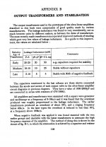
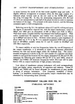
stabilising amplifiers
. The design Sandyg is using was developed by GEC who developed the KT88. The cathode followers are used to give a low impedance drive to the KT88’s I have built lots of these amps they sound excellent and the KT88/6550 last a long time. His problems with Sq waves are more likely to be with his output transformers than the circuit. I have found adding a 4700k resistor and a 470PF across the Ht to the voltage amp before the phase splitter works very well with output transformers with some leakage inductance to restrict the frequency response.
Also adding the capacitors and resistors between the Anode and screen.
May be he needs to reduce the feedback 12Db is plenty,if your output transformer is not of very high quality.
Phil
Attachments
Kingneb,
Slewing particularly with cathode followers? Not if the design is correct; limited slew rate is a general danger with any amplifier design and should be kept in mind, but need not be the biggest headache.
With the higher current and keeping the signal swing away from bottoming out (i.e. going to too low anode current on negative signal peaks) as suggested by my changes in post #77 for this design, I do not foresee that although I obviously did not analyse the complete amplifier. Perhaps the caution regarding cathode followers can be re-quoted here if someone recalls?
Regarding SandyG's problems with square wave performance comment was also given. The higher frequency component visible on the change-over parts of the signal is usual for many output transformers (mostly in the 70 - 100 KHz region). It concerns the sectionalising of the transformer; there are conflicting design requirements.
A too severe RC-attenuation required (usually bypassing the plate load of the first stage) can cut into the audio band (as with some op-amps - oops sorry! This is a tube thread ...) leading to unacceptable high-order harmonic products depending on the rest of the design, etc. To my thinking power stage oscillations/instability should and mostly can be cured there. The effect of capacitor bypassing the feedback resistor is also too often ignored. That is a leading phase correction somewhat countering the other lag corrections; often one has to optimise with a cap in series with a small resistor there.
I am against forfeiting NFB because of threatening instability by phase shifts which could be addressed. There are perfectly stable tube designs out there with >26dB of global NFB (or are some still supporting the myth of "feedback-is-bad"?). The inherent stability of an amplifier can be checked by instruments at our disposal, before and after construction. Remedies are normally only by changing/adding capacitors-resistors.
Johan, understand changes are for my original circuit, I tossed in the Grommes so you could see where some of the ideas I 'borrowed' were from.
I have on the PCB a place for raising the filaments as needed, just have to drop in one resistor.
Have not had much chance to do anything on the circuit this week, maybe this weekend I will have a few parts changed out and take a look.
Going to have to look at all these post to get a repeatable plan going. I think a few of the easy ones I can do as I have the required parts on hand. Will have to see if I can get a few of the other parts to try.
Sandy
Last edited:
....just have to drop in one resistor.
and if some more place, a bypass cap from that dc point to earth - say 8 µF 250V or so. Heaters need to be earthed (or bypassed to) to avoid stuff getting through from the power transformer to the 'live as in signal' cathodes.
Jumping back into this a bit. Did a few tests to restart.
1. Added a 68pf cap across the 20pf cap (C17) to check if any noticeable difference could be seen in the waveform at 10khz. DIDN'T SEE ANY
2. Added a 220pf cap across the 20pf cap (C17). DIDN'T SEE ANY
I have a larger variable cap on it's way to see if I'm not able to see anything but it's actually helping. Will have that in a few days hopefully.
I also removed the Screen Grid capacitors C26 and C18 (100pf) to see if it had any effect on square wave shape or stability. No change in waveform, and no stability issues as in unstable output at idle or at 1khz and 10khz. Seems that they could be in or out. My preference is to put them back in just in case.
Bias seems stable, no creeping up, but need to get a few parts to lower the path to ground and yet keep dissipation in the VR1- VR4 safe. Going to replace the 50K pots with 25K and on R50,R52,R54, R56 replace with 50k and see how that works. I think the current circuit is fine, I ran the amp for an 30 minutes or so at 75Watts and about the same at No Signal in with nominal drift in bias and no red tubes.
Pending changes -
Replace R60 from a 33k resistor to a 27K resistor
Replace R39 and R31 with a 33K resistor at 5 watts for starters. I think that 22k may push the total power dissipation on the 6SN7's close to the edge.
Also after these changes to see if any effect, try replacing the 4.7K R9 with a 6.8k as the overall voltage to the drivers seem a bit high when running solid state rectifiers.
Also don't remember what I ran power levels before for RMS output but came close to 121 Watts before it clipped with KT88's.
All of the prior tests were at 10khz with a 10v or so RMS output into 8 ohms.
(Note that the really ugly square waves in a much previous post were done at 22vrms)
Off to find some parts")
Sandy
1. Added a 68pf cap across the 20pf cap (C17) to check if any noticeable difference could be seen in the waveform at 10khz. DIDN'T SEE ANY
2. Added a 220pf cap across the 20pf cap (C17). DIDN'T SEE ANY
I have a larger variable cap on it's way to see if I'm not able to see anything but it's actually helping. Will have that in a few days hopefully.
I also removed the Screen Grid capacitors C26 and C18 (100pf) to see if it had any effect on square wave shape or stability. No change in waveform, and no stability issues as in unstable output at idle or at 1khz and 10khz. Seems that they could be in or out. My preference is to put them back in just in case.
Bias seems stable, no creeping up, but need to get a few parts to lower the path to ground and yet keep dissipation in the VR1- VR4 safe. Going to replace the 50K pots with 25K and on R50,R52,R54, R56 replace with 50k and see how that works. I think the current circuit is fine, I ran the amp for an 30 minutes or so at 75Watts and about the same at No Signal in with nominal drift in bias and no red tubes.
Pending changes -
Replace R60 from a 33k resistor to a 27K resistor
Replace R39 and R31 with a 33K resistor at 5 watts for starters. I think that 22k may push the total power dissipation on the 6SN7's close to the edge.
Also after these changes to see if any effect, try replacing the 4.7K R9 with a 6.8k as the overall voltage to the drivers seem a bit high when running solid state rectifiers.
Also don't remember what I ran power levels before for RMS output but came close to 121 Watts before it clipped with KT88's.
All of the prior tests were at 10khz with a 10v or so RMS output into 8 ohms.
(Note that the really ugly square waves in a much previous post were done at 22vrms)
Off to find some parts
Sandy
Few further points (not trying to dominate discussion):
Multi,
I take it you meant 4,7K for R60, not 4700K? Then R60.C30 would 3dB at about 7kHz - cutting somewhat into the audioband; still. The present pole is at 50kHz and will not really do much because of the magnitude of R60.
In fact, the output transformer for which the present values and those for R19.C17 and C18, C26 will work must be of super quality. The present C17.R19 comes in at only 1,2 MHz, while C18, C26 will have an effect at >500kHz depending.
So Sandy,
With your present changes I do not expect to notice a difference. You might start to see a change with C17 > 560pF, while C18, C26 might only begin showing an effect at >1nF. Start by trying with C17 = 680 pF, but watch out for instability, since I do not know your OPT.
With R31, R39 of 22K the triodes will dissipate 2W each. The max. spec for both triodes working is pa = 3,7W each, so you may in fact decrease those R's.
Johan -
The variable cap i'm waiting for is a dual section 365pf unit and I'll try that to see how it works without doing the solder and retry. I should just pop it into a case with a variable resistor and make a 'feedback' box...
I have parts on the way for the 22k 5watt's as well as bias fixes.
I mis-read the power dissipation on the 6sn7's I first thought total power was 5 watts with peak of 3.5 per half. Actually in re-reading the datasheet it s 5 watts individually with a max total of 7.5watts. So all should be good.
I think the only think that I had not removed to get a baseline test was the zobel filter on the output 8 ohm tap. Going to remove that just to make sure it's not affecting anything...
Moving slowly along
Sandy
Some parts showed up today.
So started working on the Bias circuit a bit. I changed out the 100k R51, R53, R55, R57 to 51k as a starter. Left everything else as it was. Bias seems like it's in a better range. At the maximum bias tubes are drawing about 42ma so range will allow me to bias up the KT88 better then before. The question for the bias circuit is the 100K resistors that go to the grid resistors (R50, R52, R54, R56) should I also try to reduce those to a lower value? I think most KT88 circuits I have seen all run with 100k on that part of the circuit.
I have 22k and 33k 5 Watt resistors for R31 and R39 and the changes for R29 and R35 (5.1k). So will give that a shot.
Also have the 365pf dual section (730pf total) variable cap to give the feedback circuit another try too.
Sandy
Some progress...
I tossed the variable cap on C17 and watched what it did to the square wave. And at first all it looked like it was doing was rounding off the edges. I also saw some instability (as Johan said it would) as I started to bring it up towards the end of the range (maybe 600pf).
Then I looked again and slowly put capacitance into the circuit. Ended up cleaning up the square waves LEADING edge a bit with about 470pf of cap for C17. It took out the bit of ripple that was seen right at the beginning of the square wave.
The trailing edge of the wave maintained it's original shape for the most part.
Some progress.
I also added a 220k 2 watt resistor (R10) to the center tap of the 6.3Vac on the 6SN7's with what looks like an 88v potential to the heaters. That should keep the heater to cathode voltage in range for the CF.
More to come.
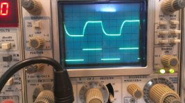
Ok, finally did all the Johan recommended modifications. I updated the 4.7K resistors R29 and R35 to 5.1K and swapped R60 to 27K.
Then messed with R31 and R39. First trying the recommended 22k 5w and didn't see much changes on the output shape at 10khz. I looked at the square wave and looked smooth but not so square. I also didn't see any noticeable change when I backed off to 33k 3W for R31 R39. I decided to leave in the 33k for the sake of tube life.
Other then that seems like with those changes can go on to build the second one and try them out as a pair. It sounded very good with one channel and other other another home made KT88 (50 Watts or so) amp. Still need the pair to really hear how good they sound.
Need to order another power trans/output from Heybor and ordered a chassis from Landfallsystems.com who makes really nice custom sized cases that are way better then the Hammond crap.
Attached is the 10khz waveform at something like 15V RMS into 8ohms.
Sandy
Attachments
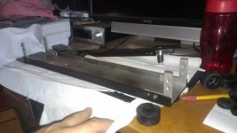
Been a while waiting for the power transformers and the chokes. They arrived a week or so ago and I stated working on the chassis. The chassis was from Landfall systems and were size to about 10"x17" in raw finish. I opted to try the paint route vs. anodizing them. Here is their site, and I can very strongly recommend these chassis for your projects!
https://www.landfallsystems.com/
https://www.landfallsystems.com/
Attachments
6550 x 4 amp
A different way to make a similar the amp
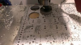
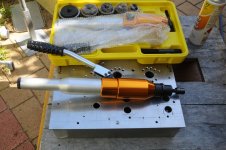
I too am just making a 4 X 6550 amplifier, using a Chinese metal punch.
I am using 6n6T x 2 and 6bl7 x 2 based on the GEC x 8 Kt88 amp.
The top plate is 4 mill ali; I am having it powdered coated.
will use a Sowter out put transformer and Chinese made c core transformers.
The Chinese made metal punches are very good.
Phil
A different way to make a similar the amp
I too am just making a 4 X 6550 amplifier, using a Chinese metal punch.
I am using 6n6T x 2 and 6bl7 x 2 based on the GEC x 8 Kt88 amp.
The top plate is 4 mill ali; I am having it powdered coated.
will use a Sowter out put transformer and Chinese made c core transformers.
The Chinese made metal punches are very good.
Phil
Attachments
Rather then punching / drilling chassis its much better to order laser or water jet abrasive CNC cutting.
Laser cutting is good for sheet steel (not stainless), and water jet abrasive for everything else. Very high precision, will require few polishing with sand paper.
Google for companies available around for this kind of service.
Laser cutting is good for sheet steel (not stainless), and water jet abrasive for everything else. Very high precision, will require few polishing with sand paper.
Google for companies available around for this kind of service.
In Perth Australia laser cutting costs a lot of money and is only affordable if you are making lots of the same amplifier; not suitable for one offs. i think would be the same in any country
My punch set cost about $A180.00 less than the cost for one die for the japanese sets.
has dies from 20-63.
Phil
My punch set cost about $A180.00 less than the cost for one die for the japanese sets.
has dies from 20-63.
Phil
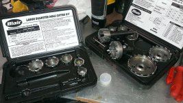
The punch kit looks cool, not too expensive, but I don't know how they would work with 1/8" (.125) aluminum. That might be a struggle for them to do a clean hole. They are cool, and not too expensive on Ebay, some larger sized rams (10T and 15T) for not much more.
The Rotabroach and the Holesaw kits I use leave a perfectly clean hole, no sharp edges, and are available in a lot of intermediate sizes too. About $140 for both kits as I recall.
I did these on a small drill press, but previously just used a 1/2" Dewalt 18V drill with good results.
Laser/Water/etc are all readily available here but for only a couple of boxes (as mentioned) they are cost prohibitive unless you have a friend with one and will let you use it (Still working on that). Set up fees and time on the machine are still not cheep. Water Jets are getting ousted out of some shops here in California due to EPA waste byproducts as I was told. Who knows...
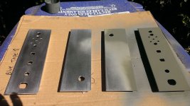
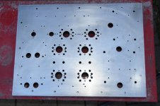
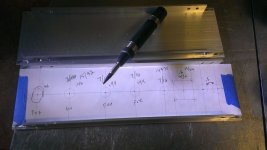
The hole saws and rotabroach are fast and give excellent results even on the thick chassis material that I have and make short time of the work, just stick on a paper template and center punch then drill.
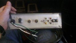
The harder ones to fabricate are things like the things on the back panel as you need to do some hand filing to make things fit with the strain relief, fuse holders and bias taps.
All part of the fun!
Sandy
The Rotabroach and the Holesaw kits I use leave a perfectly clean hole, no sharp edges, and are available in a lot of intermediate sizes too. About $140 for both kits as I recall.
I did these on a small drill press, but previously just used a 1/2" Dewalt 18V drill with good results.
Laser/Water/etc are all readily available here but for only a couple of boxes (as mentioned) they are cost prohibitive unless you have a friend with one and will let you use it (Still working on that). Set up fees and time on the machine are still not cheep. Water Jets are getting ousted out of some shops here in California due to EPA waste byproducts as I was told. Who knows...
The hole saws and rotabroach are fast and give excellent results even on the thick chassis material that I have and make short time of the work, just stick on a paper template and center punch then drill.
The harder ones to fabricate are things like the things on the back panel as you need to do some hand filing to make things fit with the strain relief, fuse holders and bias taps.
All part of the fun!
Sandy
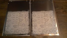
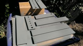
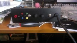
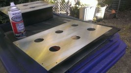
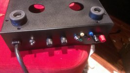
Here are a few more pics. Primer is self etching and paint is texture black which gives a nice non-glossy finish much like the paint on old dynaco's and other amps from the era. The Landfall box is easily assembled and easy to add parts prior to that. Makes it easy to tighten things up that are hard to get to while in a box that doesn't have panels. Back panel is ready to go, as well as bottom panel that has some large bumpers used as feet. The bottom panel will get some screen mesh over the larger air vents.
Making some progress!
Sandy
Making some progress!
Sandy
Attachments
-
 EZ125_All_Side_Panels_Primer.jpg141 KB · Views: 72
 -
 EZ125_Assembling_Chassis.jpg93.4 KB · Views: 61
 -
 EZ125_Back_Panel.jpg98.1 KB · Views: 60
 -
 EZ125_Back_Of_Back_Panel.jpg82.9 KB · Views: 68
 -
 EZ125_Stuffed_Back_Panel.jpg102.4 KB · Views: 72
 -
 EZ125_Bottom_Panel.jpg128.7 KB · Views: 73
 -
 EZ125_Mock_Bottom_Assembly.jpg133.1 KB · Views: 73
- Status
- This old topic is closed. If you want to reopen this topic, contact a moderator using the "Report Post" button.
- Home
- Amplifiers
- Tubes / Valves
- EZ125 Quad KT88 Project