I have a question relating to line stage with tall bias, such as a 6V6 preamp with a bias of -10V or so.
I understand one rationale behind putting the volume control in front of the line stage is that the stage will then never see anything close to an overload condition, so distortion will be minimized. In the typical preamp using something like a 6SN7 or 5687 tube with a bias of maybe -4V, a 2Vrms signal applied at its input can come close to overloading the stage, causing distortion to increase.
However, if I have a 6V6 line stage (like Salas') with a grid bias of around -10V or more, even that 2Vrms signal shouldn't come close to overloading it. Does it now make sense to consider putting the volume pot (or stepped attenuator) on the output of the preamp, instead of at the input? Or does that cause frequency response errors due to a changing resistance on the output of the preamp stage?
What if the tube used for that preamp has a plate resistance of well less than 1000 ohms (and a mu below 10), and I use a 50k ohm pot on its output?
I don't know enough to identify all the issues that might be involved, and I'm hoping to gain a better understanding. Thanks for any advice you can send this way.
-=|=-
Hi!
If you want to use a resistive volume control, like a 50k pot, don't put it at the output. It will cause a rather high output impedance (depending on the volume setting) Which kinda defeats the purpose of such a beefy line stage driver.
I use transformer volume controls in my preamps and put them at the output. In this case the output impedance also changes with volume setting, but gets lower as the volume is turned down and at setting like -12dB is in extremely low territory.
Best regards
Thomas
In order not to increase the output impedance of the preamplifier you will need to use a low value output pot.
You are placing a heavier load on the output load (the volume control is in parallel with the volume control) which will increase distortion.
I do not see any practical implementation which could achieve an output impedance lower than about 10K, when a well designed valve preamp could achieve output impedances of less than 200ohms.
Really I cannot see any good reason to put the volume pot at the output, unless you buffered it after volume pot - which is not desirable either.
Shoog
Why do you find a buffer after the pot 'not desirable'?
More noise, hum, and signal degradation.
The fewer components in the path, the better.
I see. What I don't understand is how this is different than having the volume control at the input of your power amp, with the sources feeding it. Is that because the sources (like a CD player) will have solid state output stages?
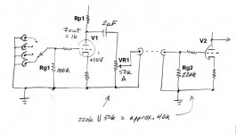
I whipped up a drawing to illustrate the proposed location of the pot.
Assume the output resistance of V1 is 1k ohms.
The grid bias on V1 is -10V.
Does adjusting the pot (VR1) change the output resistance from V1, as seen by the grid of V2?
I whipped up a drawing to illustrate the proposed location of the pot.
Assume the output resistance of V1 is 1k ohms.
The grid bias on V1 is -10V.
Does adjusting the pot (VR1) change the output resistance from V1, as seen by the grid of V2?
Attachments
Last edited:
Hmmm... I see that a few folks here need to remember Thévenin's theorem... which states that resistive voltage-dividers have in impedance equal to the pair of resistances in parallel (R1 R2)/(R1 + R2) equivalently in series with a voltage source that is VR2/(R1+R2) volts.
IN other words, the impedance goes down as a tail-attenuator is swept progressively toward R2 = 0 ohms. One just has to remember that there's the pair of "resistances" in the gain stage - the plate-to-power-rail resistor, and the plate resistance itself, these, in parallel with the R1+R2 of the output attenuator pot.
The use of a "tapped transformer attenuator" is wickedly wonderful stuff, but doesn't actually achieve remarkably much more than a resistance divider (AKA "pot") derives.
The only "problem" will be finding a match between the output impedance of the gain stage and the "unattenuated" position of the interstage attenuation pot, AND the input stage of the amplifier that follows.
I've done a fair amount of experimenting with this over the years, and I find that it only "works" if the amplifier input stage has fairly high input impedance, say, 100K+ Then without too much attenuation, a 100K audio-taper pot can be used quite practically. Typically, its insertion at least attenuation causes about a -3 dB overall gain drop. Usually not an issue.
GoatGuy
PS: I also like a 4-pole ganged pot configuration - which attenuates BOTH the input and the output in lockstep. Oh, sure, could be 2 pole (simple stereo), giving the experimenter some control over the relative degree of preamp stage distortion, to "find a sweet spot". But usually once the values are known, the "next amplifier" can have the 4-gang pot. Since "4-gang" pots are rare, I usually resort to stepped attenuator switches. Lots of those around. Just need 4 disks.
GG
Assume the output resistance of V1 is 1k ohms.
The grid bias on V1 is -10V.
Does adjusting the pot (VR1) change the output resistance from V1, as seen by the grid of V2?
Yes. When the pot is at the top, the output resistance is close to the 1K of the tube. At the bottom it is zero. Close to the half way point is the worst case when it will be 51/4 K or just under 13K. The -3dB point of 13K and 100pF of cable capacitance is about 122KHz.
A preamp with a 1K output impedance ought to be able to drive a 10K load. Using a 10K pot would make the worst case output impedance 2.75K.
Cheers
Ian
A pot at the input of a power amp does not have much cable to drive. Put the same pot at the output of the line stage and it drives the interconnect cable; that means a smaller resistance may be needed and hence more distortion in the previous stage.rongon said:What I don't understand is how this is different than having the volume control at the input of your power amp, with the sources feeding it.
Thanks GG and Ian for the explanation of the resistances and how they change the load seen by the subsequent stage.
OK, that certainly makes sense. A larger value pot before a one meter stretch of interconnect cable (with about 200 to 300pF capacitance) will make a low-pass filter whose pole frequency varies with the position of the pot. Reduce the value of the pot to compensate and it becomes a more difficult load for the line stage to drive.
But what about the case where the pot is after the input switch, at the input of the line stage? That becomes the load for the source devices. Say I have an RIAA preamp with an output resistance of about 2k ohms. With the volume control at the input of the line amp (or "integrated" amp), the interconnect cable, input switch and that volume control collectively define the load the RIAA preamp sees on its output. So isn't that same loading problem now transferred to the output of the RIAA preamp, instead of the line stage output?
Is that why RIAA preamps have such low output resistance (cathode follower)? Does the output resistance of the RIAA stage need to be a few hundred ohms, in order to drive a meter of cable and the pot/vol ctrl, without creating an external low pass filter?
--
A pot at the input of a power amp does not have much cable to drive. Put the same pot at the output of the line stage and it drives the interconnect cable; that means a smaller resistance may be needed and hence more distortion in the previous stage.
OK, that certainly makes sense. A larger value pot before a one meter stretch of interconnect cable (with about 200 to 300pF capacitance) will make a low-pass filter whose pole frequency varies with the position of the pot. Reduce the value of the pot to compensate and it becomes a more difficult load for the line stage to drive.
But what about the case where the pot is after the input switch, at the input of the line stage? That becomes the load for the source devices. Say I have an RIAA preamp with an output resistance of about 2k ohms. With the volume control at the input of the line amp (or "integrated" amp), the interconnect cable, input switch and that volume control collectively define the load the RIAA preamp sees on its output. So isn't that same loading problem now transferred to the output of the RIAA preamp, instead of the line stage output?
Is that why RIAA preamps have such low output resistance (cathode follower)? Does the output resistance of the RIAA stage need to be a few hundred ohms, in order to drive a meter of cable and the pot/vol ctrl, without creating an external low pass filter?
--
Last edited:
Hi!
Normally you would have rather short lengths of cable between sources and line stage and potentially longer cable runs to the power amp. So ideally a linestage presents an easy load to the sources. Typically that is 47kOhm. Any source should be able to drive that. Of course it is beneficial to have low output impedance at the sources. But you can get away with a few kOhms.
When the volume pot is at the input side of the line stage, after the input selector, it should be of higher impedance, 50 or 100kOhm, in order not to load the sources too much.
The linestage should act as an buffer between the sources and power amps (in addition to it's duty to provide a means for input selection and volume control).
Best regards
Thomas
A competent phono preamp will be designed to drive a reasonable length of cable, possibly followed by a volume pot. Remember, the input to a volume pot sees typically the pot value (so a relatively easy load); the output sees up to a quarter of the pot value (so a relatively weak source).
A competent phono preamp will be designed to drive a reasonable length of cable, possibly followed by a volume pot. Remember, the input to a volume pot sees typically the pot value (so a relatively easy load); the output sees up to a quarter of the pot value (so a relatively weak source).
OK, I'm learning again, I think. (Thanks for this!)
If I have a line stage whose plate load||internal plate resistance is about 1k5, followed by a 100k pot, which is then followed by 300pF from a meter of interconnect cable, into a power amp with a 220k grid leak resistor, what are the problems introduced?
Let's say the load the 100k pot presents to the line amp output is 25k ohms at its minimum. So that would be 25k in parallel with 220k, or 22.45k ohms load on the line stage output.
If that's what happens, then I can see what the problem is. The above combined with 300pF of cable capacitance makes a low pass filter with a corner frequency of only 22.36 kHz.
Did I get that close to right?
--
100k pot imposes a load of 100k (roughly). It sources at a maximum of 25k (at the -6dB point).
In your case the worst load seen by the line stage will be at maximum volume: 100k parallel to 220k and 300pF.
The worst case for driving the output will be around -6dB volume, when the source will be 101.5k/4 feeding 220k||300pF. This accords with your calculation, but not your description.
In your case the worst load seen by the line stage will be at maximum volume: 100k parallel to 220k and 300pF.
The worst case for driving the output will be around -6dB volume, when the source will be 101.5k/4 feeding 220k||300pF. This accords with your calculation, but not your description.
- Status
- This old topic is closed. If you want to reopen this topic, contact a moderator using the "Report Post" button.
- Home
- Amplifiers
- Tubes / Valves
- tube preamp vol ctrl -- before or after?