OK. In which case you really need to read a book on elementary electronics before going any further. Horowitz and Hill is the standard text book for electronics and fortunately you can download a copy of one of the older editions for free. Google is your friend.
Cheers
Ian
Google "electronics on-line courses" There are MANY with at varying levels. MIT has their "101" class on-line and free but warns that to do well you should have completed a high school AP physics class Other on-line classes start by connecting a battery to a light bulb. You can find one that "fits". But make sure it at least covers "AC circuit theory" You need to know what reactance is and why impedance is a complex number.
The above book is good if you ignore the way-outdated digital stuff.
There really are some great online classes I'm currently re-learning linear algebra and organic chem at Kahn Academy. and don't forget pole's iTunes-U, many free video'd lectures there also.
About how to connect the transformer. Yes you can use the transformer as a load but it requires math and a complete redesign. That WOULD be the best way to go. But for now tacking on a 1:1 using a capastor to block any DC current will let you experiment.
A good sours of ideas if you don't want to re-invent stuff is Jenson's web site. They have some good designs that use their transformers
JENSEN TRANSFORMERS, INC. - APPLICATION SCHEMATICS
You can make something my combining one of there microphone front ends with a line out driver.
The grounding problem is easy to understand when you remember that any time current flows there is a voltage drop. So your "ground wire" is not at zero volta if there is current in it.
Guys thanks for suggested books. I'll try to find and read them.
Of course I understand what AC coupled means. I just did not hear this term before.")
Jensen http://www.jensen-transformers.com/as/as021.pdf shows exactly what I meant by a option "one". Another option would be connecting OT's primary to anode of lower tube in mu-follower and to cathode resistor of upper tube, instead of anode resistor.
I've simulated both in LTSpice, it shows better results for primary as a load. Also, it can be possible to remove capacitor from there making this DC coupled, if a transformer allows DC. The cap can create resonance with inductance of primary.
What will be sonically better, I do not know. I think it totally depends on OT. Unfortunately I cannot buy multiple OTs for testing, too expensive.
Thus any recommendations on OTs are welcome.
Zout is 88 Ohm, mu-follower. Zin is 10KOhm balanced.
On Lundahl site I've found many different transformers. Same on Jensen site, but there not many can be balanced. Did not check Sowter others yet.
Of course I understand what AC coupled means. I just did not hear this term before.
Jensen http://www.jensen-transformers.com/as/as021.pdf shows exactly what I meant by a option "one". Another option would be connecting OT's primary to anode of lower tube in mu-follower and to cathode resistor of upper tube, instead of anode resistor.
I've simulated both in LTSpice, it shows better results for primary as a load. Also, it can be possible to remove capacitor from there making this DC coupled, if a transformer allows DC. The cap can create resonance with inductance of primary.
What will be sonically better, I do not know. I think it totally depends on OT. Unfortunately I cannot buy multiple OTs for testing, too expensive.
Thus any recommendations on OTs are welcome.
Zout is 88 Ohm, mu-follower. Zin is 10KOhm balanced.
On Lundahl site I've found many different transformers. Same on Jensen site, but there not many can be balanced. Did not check Sowter others yet.
I've added cheap $5 600x600 Mouser transformer as AC coupled load. It shows excellent noise elimination, that buzz disappeared. JNoisemeter shows SNR 83dB (unfiltered, RMS)
The only residue of buzz is left that is picked up by umbilical cable. Probably it needs to be shielded, or/and twisted better. Currently I use 5 wire electrical cable from Lowes. May be I need to make DIY one, shielded.
So, I'll go with an output transformer, do not know which one.
The only residue of buzz is left that is picked up by umbilical cable. Probably it needs to be shielded, or/and twisted better. Currently I use 5 wire electrical cable from Lowes. May be I need to make DIY one, shielded.
So, I'll go with an output transformer, do not know which one.
On Lundahl site I've found many different transformers. Same on Jensen site, but there not many can be balanced. Did not check Sowter others yet.
All transformers are inherently balanced. I think you need to do some more reading!!!
I am pleased that a transformer fixed your hum problem.
Transformers do have trouble carrying dc. It can saturate the core. To avoid this an air gap is introduced into the core. The stops the saturation but significantly reduces the inductance. Inductance defines the reactive load the transformer itself presents. Ideally this should be as high as possible. Hence inductance should be as high as possible. For a given core, the inductance of a transformer with no gap will be a lot higher than one with a gap. This is one reason the PP output transformers tend to be so big and expensive. If you ac couple then there is no dc in the transformer and you can use one without a gap, get higher inductance and better bass response. So I recommend the ac coupled method. The output capacitor will resonate with the transformer inductance but if it has no gap the inductance will be high and the resonance will be well below the audio band. The resonance is damped by the amplifier output impedance.
Cheers
Ian
thanks, Ian. Saying "balanced" I meant "with secondary center tap".
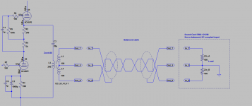
I believe that OT should have a secondary center tap that will be connected to Sleeve (Pin 1) and further to ground and earth of downstream line amp (sound card).
I understand that there will be a balanced voltage between bottom and top ends of OT's secondary, and it will refer to each other. Well, we can hope that an arbitrary balanced input will work well without a ground reference, just getting difference between Tip and Ring. But I read also that "servo-balanced" requires Sleeve to be grounded. Though it is said that + and - signals may be not symmetrical relative to ground in this case.
I think it is more safe to connect input ground to OT's secondary center tap to satisfy all possible input topologies, while isolating ground and earth of the mic preamp from ground and earth of line amp(sound card) to break possible earth loop.
Am I right?
here I've illustrated what I want to do (and how it is currently done with the cheap OT). Please note that ground of the Preamp is different than ground of Sound card, they are disconnected. However they are most likely connected via house mains earth. But they are not connected by signal cable, the output TRS connector's sleeve is not connected to preamp's chassis, so the earth loop is not created.
Attachments
Your scheme will work fine. The transformer centre tap is not necessary though. You can just leave the screen of the cable unconnected at the transformer end. This is called a balanced floating connection and is commonly used in professional transformer balanced audio equipment.
Cheers
Ian
Cheers
Ian
Thanks Ian,
I also found at Sowter FAQ SOWTER TRANSFORMERS FAQ that grounding of center tap is not necessary and sometimes is even harmful.
I also found at Sowter FAQ SOWTER TRANSFORMERS FAQ that grounding of center tap is not necessary and sometimes is even harmful.
I do not think it will ever plugged into a PP tube amp, but I will consider to add a switch if I'll buy an OT with center tap.The only situation where you need a center tap is when you are driving a push-pull amplifier stage
Thanks Ian,
I also found at Sowter FAQ SOWTER TRANSFORMERS FAQ that grounding of center tap is not necessary and sometimes is even harmful.
I do not think it will ever plugged into a PP tube amp, but I will consider to add a switch if I'll buy an OT with center tap.
I think the reference to power amps is in the context of a centre tapped transformer being used as a phase splitter inside a PP amp rather than being anything to do with driving a tube power amp per se.
Cheers
Ian
Currently I am considering to use an output transformer at preamp output.
But reading article "Jensen AN-003 INTERCONNECTION OF BALANCED AND UNBALANCED EQUIPMENT" http://www.jensen-transformers.com/an/an003.pdf
I found following:
There is a part 2.2 - "BETTER" uses an Output Transformer to Improve Balance
and part 2.3 - "BEST" uses an Input Transformer to "Fix" the Input Stage
Difference I see is OT at output side of cable, or IT at input side of cable.
Why the second is better?
Should I consider to use an input transformer at E-MU 1212 input to "fix" input stage?
Currently I am considering to use an output transformer at preamp output.
But reading article "Jensen AN-003 INTERCONNECTION OF BALANCED AND UNBALANCED EQUIPMENT" http://www.jensen-transformers.com/an/an003.pdf
I found following:
There is a part 2.2 - "BETTER" uses an Output Transformer to Improve Balance
and part 2.3 - "BEST" uses an Input Transformer to "Fix" the Input Stage
Difference I see is OT at output side of cable, or IT at input side of cable.
Why the second is better?
Should I consider to use an input transformer at E-MU 1212 input to "fix" input stage?
It's complicated, but it is partly because the OT they use in that example is really an input transformer and it does not work too well as an OT. If you use a 600:600 OT then its performance will be fine.
Cheers
Ian
...
Should I consider to use an input transformer at E-MU 1212 input to "fix" input stage?
You would have to re-build the E-MU 1212. Simply placing a transformer between the preamp and the audio interface does not change the audio interface it would still have a differential amplifier inside that is made of op-amps.
They also say that a rebuilt will be more efficient, but placing IT right in front of input also works. The input transformer isolates cable capacitance and possible cable imperfectness, that can cause unbalance, from an input stage.You would have to re-build the E-MU 1212. Simply placing a transformer between the preamp and the audio interface does not change the audio interface it would still have a differential amplifier inside that is made of op-amps.
I assume the difference between "OT interface" and "IT interface" performance will be more pronounced when a cable is long. With short cables difference should be small.
Here is another article that describes IT and OT differences http://www.jensen-transformers.com/an/an002.pdf.
Last edited:
Hi Ian,It's complicated, but it is partly because the OT they use in that example is really an input transformer and it does not work too well as an OT. If you use a 600:600 OT then its performance will be fine.
Hmm. Why do you think that JT-11-EM is IT?
They have now JT-11-ELCF http://www.jensen-transformers.com/datashts/11elcf.pdf that is OT same as JT-11-EM except its different core.
I barely understand how it works, I think that they wrote that IT can do better then OT because it excludes unbalances of cable, caused by different capacities between wires 1-2 and 1-3 - secondary of IT has short leads to input stage with very low capacitance that can be ignored.
Also OT should have low impedance and resistance that means less turns of wire, that should decrease its self-inductance.
IT can have more self-inductance which is better for FR.
Is my understanding correct?
What do you mean by 600:600 OT? All 600:600 I've seen were cheap transformers for phone lines. I read that "600 Ohm" came from characteristic impedance of telegraph lines. Should we still use it in Hi-Fi or Pro audio?
Per Lundahl advises to use LL1588. It is interesting that it can be used as OT as well as IT.
LL1588 is a high-level general-purpose transformer which can be used for microphone or line input, for line output and for galvanic isolation.
The windings are arranged to give perfect symmetry if the transformer is used in phase splitting input applications. The two coils structure also greatly improves immunity to external magnetic fields from e.g. power supplies and motors. Primary and secondary windings are separated by electrostatic shields. The core is a high permeability mu metal core. The transformer is housed in a mu-metal can.
Hi Ian,
Hmm. Why do you think that JT-11-EM is IT?
They have now JT-11-ELCF http://www.jensen-transformers.com/datashts/11elcf.pdf that is OT same as JT-11-EM except its different core.
I barely understand how it works, I think that they wrote that IT can do better then OT because it excludes unbalances of cable, caused by different capacities between wires 1-2 and 1-3 - secondary of IT has short leads to input stage with very low capacitance that can be ignored.
Also OT should have low impedance and resistance that means less turns of wire, that should decrease its self-inductance.
IT can have more self-inductance which is better for FR.
Is my understanding correct?
What do you mean by 600:600 OT? All 600:600 I've seen were cheap transformers for phone lines. I read that "600 Ohm" came from characteristic impedance of telegraph lines. Should we still use it in Hi-Fi or Pro audio?
The Jensen JT-11-ELCF IS a 600:600 transformer. You are right it is an output transformer. It is confusing because the JT-11-ELCF is a 600:600 output transformer and the JT-11P-1 is a 10k:10k input transformer. I mistakenly thought they were using the SAME transformer in both examples when in fact they were quite different. Sorry to have added to the confusion.
The bottom line is Jensen is right. If there is just a single transformer, it is best at the input end of an unbalanced connection. The ideal situation of course is a transformer at each end.
Cheers
ian
Ian thanks for clarification!
Balancing network would comprise of 20uF capacitor and 70 Ohm resistor serially between ground and wire #3.
I also thought about it, may be even OT is 1:4 and IT is 4:1 will be more efficient. But as a less expensive alternative, will be an impedance balancing network at output side and IT at input side work better than just unbalanced output with IT?The ideal situation of course is a transformer at each end.
Balancing network would comprise of 20uF capacitor and 70 Ohm resistor serially between ground and wire #3.
Ian thanks for clarification!
I also thought about it, may be even OT is 1:4 and IT is 4:1 will be more efficient. But as a less expensive alternative, will be an impedance balancing network at output side and IT at input side work better than just unbalanced output with IT?
Balancing network would comprise of 20uF capacitor and 70 Ohm resistor serially between ground and wire #3.
Yes, impedance balanced output and an input transformer should work well and be relatively cheap. I think a lot of this is academic. The main thing for your original hum problem is to break the signal ground connection between the mic pre and the PC.
Cheers
ian
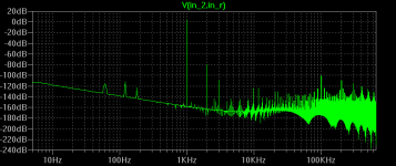
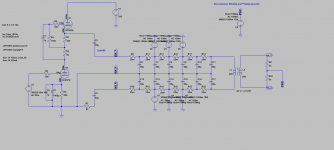
I've simulated the OT, IT with and without Output Impedance Matched Passive Network in LTSpice.
Cable is 6-ft, R 25mO/f, C 50pF/f.
Noises: sinusoidal signals 60,120 and 180Hz, 1V, common mode to both wires.
OIMPN -> 6ft cable -> IT
It shows up to 40dB lower buzz comparing to simple unbalanced output. It shows just little spikes of buzz a little bit above -140dB.
The result is very very close to results for OT -> 6ft cable -> IT.
However with OT it does not have any little spike of buzz at all.
OT -> 6ft cable -> bal load R10k - gives random noise floor around -120dB
So, the best result was, of course, OT-to-IT coupling. Very close to it, but 2 times cheaper - OIMPN to IT.
It is interesting, direct connection with floating pin 1 on output side shows very clean result - full common noise rejection (however in real life this allows some buzz).
Same results with direct connection from OIMP with grounded pin 1.
It is interesting, direct connection with floating pin 1 on output side shows very clean result - full common noise rejection (however in real life this allows some buzz).
Same results with direct connection from OIMP with grounded pin 1.
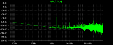
Actually picture become more realistic, after I've added buzz voltage between MicAmp ground and PreAmp ground.
OIMPN cancels EMI and buzz very efficiently even without IT.
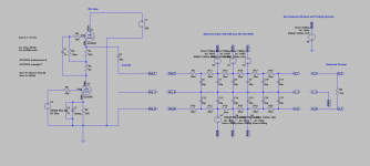
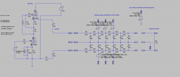
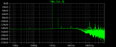
Here are schematics and FFTs of:
1 - unbalanced output to servo-balanced input
2 - OIMPN balanced output to servo-balanced input
3 - OIMPN balanced output to IT balanced input
Attachments
- Status
- This old topic is closed. If you want to reopen this topic, contact a moderator using the "Report Post" button.
- Home
- Amplifiers
- Tubes / Valves
- Ribbon Microphone Preamp