As others have said, gm varies widely with plate current. Mu is approximately constant and both mu and gm vary with plate current. Look at page 8 of this data sheet for grapphs of gm, mu and ra versus plate current:
http://www.wooaudio.com/docs/tube_data/6922(E88CC).pdf
Now you can see why tube manufacturers tend to specify tube parameters at a high plate current because if make mu and gm high and ra low.
Cheers
Ian
http://www.wooaudio.com/docs/tube_data/6922(E88CC).pdf
Now you can see why tube manufacturers tend to specify tube parameters at a high plate current because if make mu and gm high and ra low.
Cheers
Ian
There is another solution maybe.
I have seen the Samar site and the products seems to be very interesting.
But Sowter, p.e., has some products that can be ordered with OCC wire to decrease the Rdc. With a ratio of 1:20 (26 dB)
Regarding the tube, try to use a cheap EF184 triode connected; it has a mu of 55 but an internal Rp of 3,5 kohm (about) so the his noise figure is quite low. The gm is 15 mA/V
With a low level input signal the 2nd harmonic is very low.
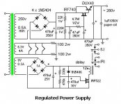
Regarding power I suggest you to use a solid state regulator circuit with a very low output impedance to kill the residual noise comes from rectification (region around 50-60 to 400 Hz).
I found this schematic
Walter
I have seen the Samar site and the products seems to be very interesting.
But Sowter, p.e., has some products that can be ordered with OCC wire to decrease the Rdc. With a ratio of 1:20 (26 dB)
Regarding the tube, try to use a cheap EF184 triode connected; it has a mu of 55 but an internal Rp of 3,5 kohm (about) so the his noise figure is quite low. The gm is 15 mA/V
With a low level input signal the 2nd harmonic is very low.
Regarding power I suggest you to use a solid state regulator circuit with a very low output impedance to kill the residual noise comes from rectification (region around 50-60 to 400 Hz).
I found this schematic
Walter
Attachments
Last edited:
As others have said, gm varies widely with plate current. Mu is approximately constant and both mu and gm vary with plate current. Look at page 8 of this data sheet for grapphs of gm, mu and ra versus plate current:
http://www.wooaudio.com/docs/tube_data/6922(E88CC).pdf
I am trying to derive a formula that will give Vn (V of flicker and shot noise) from known values Vg, Va, Ia, and may be Mu, that I can get from LTSpice model. for a 20KHz bandwidth.
So far I've derived following:
gm = Ia / Vg
Vfn = Ia/gm * 2.6 = Ia / (Ia/Vg) * 2.6 = Vg * 2.6 (uV).
But I feel something is wrong.

No. You can get ra from the data sheet graphs. If a rough guess will do then you could assume ra=Va/Ia, to within a factor of 2.mm7 said:Is it possible to produce Ra from Ia and Vg and Va ?
No. gm = dIa/dVg, at constant Va. You could get a rough estimate of gm from mu x Ia/Va.gm = Ia / Vg
Then flicker noise will beYou could get a rough estimate of gm from mu x Ia/Va.
Vfn = Ia/gm * 2.6 = Ia / (mu * Ia / Va) * 2.6 = Va / mu * 2.6
So it mainly correlates with Va. Is it correct?
Hi,
Not IME. I'd suggest (and take it for nothing more than that) that it is always there as soon as the valve starts conducting. The other parameters in the formulae (such as gm, Ia and Va for instance) will only tend to "amplify" it somewhat.
IOW, there's nothing AFAIK that you can do about it.
Ciao,
So it mainly correlates with Va. Is it correct?
Not IME. I'd suggest (and take it for nothing more than that) that it is always there as soon as the valve starts conducting. The other parameters in the formulae (such as gm, Ia and Va for instance) will only tend to "amplify" it somewhat.
IOW, there's nothing AFAIK that you can do about it.
Ciao,
may be. but according to the formula
I see I should simply try it and measure.
An externally hosted image should be here but it was not working when we last tested it.
http://protubeaudio.webs.com/noiseformula.png in the article http://protubeaudio.webs.com/tubenoise.htm, the flicker noise (Vfn) is defined by its second part, that depends on Ia and 1/gm. and if we take mu as a constant, gm~=mu*Ia/Va, then Vfn should depend mostly on Va, not Ia, which is quite counter-intuitive.
I see I should simply try it and measure.
Hi,
the use of the formulas is just to have an idea of what can happen.
But ,in real world, different tubes of same type can give you big differences on noise indipendently form Va.
The way to follow for this type of stuff is high gm, low Rp; regarding the mu you can play with trafos ( with certain limits) that must be with a high ratio so you can save a good s/n.
Also the use of regulated power supply is mandatory ( or battery).
Check also a Cag of a tube, because you can find an high Gm tube with a high mu (6C45 p.e.) but with an high value, it will be in parallel with the secondary of the trafo.
W
As I said, you are combining approximations. The formula I gave for gm gives an estimate; I don't claim that it is accurate or gives the right variation with current or voltage. Formulas for noise often assume that the valve is working somewhere near its 'normal' regime, and are themselves usually only estimates. Hence you can't make the deduction you are making. Experiment is the way forward for valve noise, and you will then find a huge variation between samples and a variation with ageing.mm7 said:if we take mu as a constant, gm~=mu*Ia/Va, then Vfn should depend mostly on Va, not Ia, which is quite counter-intuitive.
Thermal (white) noise can be accurately calculated. So can temperature-limited shot noise (rare in audio circuits!) and partition noise. All other noise has to be measured, although rough estimates can be calculated. Don't expect to be able to calculate an optimum bias point for noise.
may be. but according to the formulaAn externally hosted image should be here but it was not working when we last tested it.http://protubeaudio.webs.com/noiseformula.png in the article http://protubeaudio.webs.com/tubenoise.htm, the flicker noise (Vfn) is defined by its second part, that depends on Ia and 1/gm. and if we take mu as a constant, gm~=mu*Ia/Va, then Vfn should depend mostly on Va, not Ia, which is quite counter-intuitive.
I see I should simply try it and measure.
I think you made the same mistake twice. When you write gm~=mu*Ia/Va you are assuming that ra = Va/Ia but it is actually dVa/dIa, in other words it is the dynamic resistance of the tube which is the SLOPE of the curve at the point Va, Ia, not the values of Va divided by Ia.
Cheers
Ian
I read about one exotic preamp with a dozen(!) or so 6S45P in parallel.
Review: NVO SPA one Phono Preamplifier | Confessions of a Part-Time Audiophile
nvoaudio
Does it make sense to look in this direction?
Actually the NVO SPA one has only one 6S45P per channel at its input.
The bigger SPA-II has a parallel pair per channel
I fear he has misunderstood the meaning of a formula I suggested.
I understand difference between dVa/dIa and Va/Ia.
I just cannot get dVa/dIa in LTSpice simulation. My feeling is, as soon as noise depends on relative values of I or V or both, then it should depend on absolute values too. I understand that K of dependency may (and does) vary depending on where we are on the curve slope.
Hi,
What is the desired S/N ratio that is required for such a mic pre?
Personally I have a MC stage using two twin triode ECC88s per channel. It's dead quiet but it won't beat a solid state design in that department.
The schematic is in the "Analogue Source" section of the forum and the last pages of Salas' Itch phono preamp discuss it as well.
I know of two designers (besides NVO) in the entire who use a raft of triodes (26 to over 50) in a distributed gain arrangement to get the noise floor down enough.
Ciao,
Time ago I have built an 8 channel, full balanced, mic tube amp.
I used a trafo in input, 26 dB from Sowter, and one 6922 for each channel.
To reach a very good s/n I used a 12 batteries of 12 Vdc /2 A each one to supply the anodes + 2 batteries of 6 Vdc-12 A, in parallel, for filaments.
The box of power supply weights about 32 kg.
This to have a reasonable time to recording a session of about 3 hrs.
Each tube was selected (Siemens gold pin) for noise and gain and the sockets was the venerable McMurdo with a gummy suspension (for microphonics).
This was the only way to get around -80 dB of s/n with a total gain of about 56-58 dB.
Walter
Then flicker noise will be
Vfn = Ia/gm * 2.6 = Ia / (mu * Ia / Va) * 2.6 = Va / mu * 2.6
So it mainly correlates with Va. Is it correct?
I think you made the same mistake twice. When you write gm~=mu*Ia/Va you are assuming that ra = Va/Ia but it is actually dVa/dIa, in other words it is the dynamic resistance of the tube which is the SLOPE of the curve at the point Va, Ia, not the values of Va divided by Ia.
I just added rough estimation of Gm to your formula. This rough estimation of Gm was advised by DF96,
and it should not be reversed as ra = Va/Ia, it should also include mu in this case, to bring it to a proper "slope" on the curve.DF96 said:No. gm = dIa/dVg, at constant Va. You could get a rough estimate of gm from mu x Ia/Va.
I cannot show it in formulae, but I have a feeling that a noise does not depend on dV or dI. It should depend on absolute values of V or I. It is like noise of rain, it depends on an energy of droplets, speed (V) and mass(E) of droplets, and number of droplets per second (I). But it does not much depend (in total, or in average) on some variations of I or V (dV or dI) during gusts of rain.
Hi,
What is the desired S/N ratio that is required for such a mic pre?
Personally I have a MC stage using two twin triode ECC88s per channel. It's dead quiet but it won't beat a solid state design in that department.
Requirement is "as quiet as possible"
It should be quiter than MC preamp.
LOMC generates 300uV signal. Ribbon mic gives 30uV after 1:37 transformer, for 60dB sound. Thanks I'll take a look at your schematic.
To waltube.
My B+ is filtered by 4 RC stages that remove ripple completely. Heater is feed from separate PSU (switch mode). There is no noise from it too. Both PSUs are remote from Preamp. If I unplug PSU from preamp, there is no change in noise level while it runs on energy from the last RC stage.
I also thinking about suspended tube sockets, because microphonics is significant. I hear ringing and I see disturbance around 16kHz area for couple of seconds after I knock a tube.
- Status
- This old topic is closed. If you want to reopen this topic, contact a moderator using the "Report Post" button.
- Home
- Amplifiers
- Tubes / Valves
- Ribbon Microphone Preamp