Howdy again, folks:
I've had this Magnavox PP stereo 6V6 amp for a while. It's actually working right now but all I did was to clean and paint the chassis, rewire the power and provide the missing cathode path because of their use of a remote Bal pot (these amps were used in consoles).
I wanted to upgrade this guy to an extent. The ground rules: no iron changes, same 6V6 finals, no extensive chassis mechanical changes.
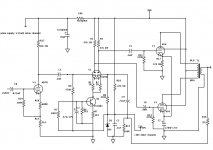
I also wanted to use some of a batch of 6DT8 dual triodes on hand (a kissing cousin to the 12AT7) and wanted to use an LTP for the PI.
The paper design is complete and attached.
The original version uses 2 ea 6EU7 tubes but there is a hole for a third 9pin. Based on how high up I have to turn my preamp to get significant output, I wanted a bit more gain. So the empty hole is being pressed into service and a third 6DT8 used to boost the overall gain by a modest factor of 9, easily changed one way or the other via the cathode gain setting (but not bias setting) resistor currently at 3.3K.
I don't want to misrepresent anything, this is finished on paper only, I have not put iron to solder yet.
Currently, I do have a scope and signal generators but no means of directly measuring THD nor IMD so I'll have to be happy with simple listening tests. The current (stock) unit has been in constant operation for about 6 months now so its sound is well known.
Someday I'll be able to get a 16b Pico scope and do full blown FFT and other measurements
But, for now, the listening test will have to do.
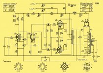
Some parts will be kept but not many. The power supply remains stock, as I said all the iron is reused and the 6V6 tubes.
While the current amp sounds surprisingly good, some of the cost saving techniques used really grate on me. Especially, the use of a common cathode resistor for all FOUR finals! Talk about inviting runaway if any of them get a little hot or cold, either way.
My implementation uses a single resistor per channel. That actually could be improved by using individual cathode resistors and individual bypass caps but, I'll start with the common pairs.
OK, that's it for now, I hope to start the actual conversion soon, will let y'all know.
Thanks!
Rene
I've had this Magnavox PP stereo 6V6 amp for a while. It's actually working right now but all I did was to clean and paint the chassis, rewire the power and provide the missing cathode path because of their use of a remote Bal pot (these amps were used in consoles).
I wanted to upgrade this guy to an extent. The ground rules: no iron changes, same 6V6 finals, no extensive chassis mechanical changes.
I also wanted to use some of a batch of 6DT8 dual triodes on hand (a kissing cousin to the 12AT7) and wanted to use an LTP for the PI.
The paper design is complete and attached.
The original version uses 2 ea 6EU7 tubes but there is a hole for a third 9pin. Based on how high up I have to turn my preamp to get significant output, I wanted a bit more gain. So the empty hole is being pressed into service and a third 6DT8 used to boost the overall gain by a modest factor of 9, easily changed one way or the other via the cathode gain setting (but not bias setting) resistor currently at 3.3K.
I don't want to misrepresent anything, this is finished on paper only, I have not put iron to solder yet.
Currently, I do have a scope and signal generators but no means of directly measuring THD nor IMD so I'll have to be happy with simple listening tests. The current (stock) unit has been in constant operation for about 6 months now so its sound is well known.
Someday I'll be able to get a 16b Pico scope and do full blown FFT and other measurements
But, for now, the listening test will have to do.
Some parts will be kept but not many. The power supply remains stock, as I said all the iron is reused and the 6V6 tubes.
While the current amp sounds surprisingly good, some of the cost saving techniques used really grate on me. Especially, the use of a common cathode resistor for all FOUR finals! Talk about inviting runaway if any of them get a little hot or cold, either way.
My implementation uses a single resistor per channel. That actually could be improved by using individual cathode resistors and individual bypass caps but, I'll start with the common pairs.
OK, that's it for now, I hope to start the actual conversion soon, will let y'all know.
Thanks!
Rene
Attachments
You're close to "classic" Mullard 5-20 topology. Why not go all the way?
A CCS in the LTP's tail is excellent, but a 10M45S is simpler than the BJT stuff shown.
You don't need "gobs" of gain from the I/P voltage amplifier. Pick a nice, linear, medium μ type. The 6FQ7 and 12BH7 are (IMO) prime candidates, for the job.
A CCS in the LTP's tail is excellent, but a 10M45S is simpler than the BJT stuff shown.
You don't need "gobs" of gain from the I/P voltage amplifier. Pick a nice, linear, medium μ type. The 6FQ7 and 12BH7 are (IMO) prime candidates, for the job.
Attachments
Much appreciated, Eli. One of my goals is to not get any new iron for this guy. I have a different, from the ground up, design which will become my eventual daily use amplifier. This one is a temporary one and it's as much an exercise in just mildly improving the "Maggie" as it is in learning a few things along the way. One of them is that if biased correctly and used kind of conservatively, the 6DT8 could do just fine. I'll find out. Certainly it is a good tube for a lower impedance driver than, say, 12AX7. Again, we'll see. Of course you are right about the CCS but I have the parts on hand, I am very comfortable designing my own current sinks and I believe this one will give me enough performance under the circumstances of original iron, etc.
The next design will be a blank sheet start, actually it's no longer a blank sheet because I have already done a lot of preliminary work, but not based on anything I already have on hand.
There is one limitation to the 10M45S and that is its BW. Its dynamic impedance does drop significantly at the higher frequencies so that needs to be considered. My simple, lower performance circuit, and others which are more sophisticated using cascaded JFETs and/or BJTs, are potentially flatter to a higher frequency.
Thanks for the circuit, though. It just might come in handy for my next, "dream" amplifier!
Rene
- Status
- This old topic is closed. If you want to reopen this topic, contact a moderator using the "Report Post" button.