Hello,
I'm not new to electronics in any way but I am to valves. I while ago I got the chance to listen to a friends valve amp on my Yamaha Ns-1000 M's and gosh altho I like my Sansui 9090-DB I would like to build a valve amp.
Now I have PCB manufacturing falsities, all the tools so forth but I dont know where to start in terms of a good circuit for my speakers... I would like an amp that will run them stress free but not too loud and needs to be diy. I have experience in High voltage AC circuits and circuit design but I have no experience in valves Any thoughts on a circut to build?
Cheers,
Thomas Fuller
I'm not new to electronics in any way but I am to valves. I while ago I got the chance to listen to a friends valve amp on my Yamaha Ns-1000 M's and gosh altho I like my Sansui 9090-DB I would like to build a valve amp.
Now I have PCB manufacturing falsities, all the tools so forth but I dont know where to start in terms of a good circuit for my speakers... I would like an amp that will run them stress free but not too loud and needs to be diy. I have experience in High voltage AC circuits and circuit design but I have no experience in valves
Any thoughts on a circut to build? Cheers,
Thomas Fuller
The Sansui 9090 DB is a 120 WPC brute of a receiver. In proper repair, it's a nice sounding piece of equipment. The Japanese, in that 1970s time frame, which preceded the era of numbers insanity, did an awful lot right, including: metal (not plastic), discrete O/P parts (not ICs), reasonable (not outrageous) levels of NFB, and attractive prices.
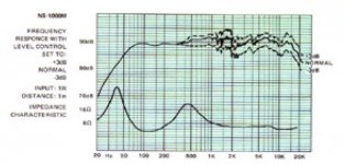
Given the fact that tube amps have smaller damping factors than SS amps, a quick look at the uploaded impedance curve suggests it might be prudent to treat those Yamaha speakers as being 6 Ω and derate them to 88 dB. sensitive. Good control of the woofer voice coil is quite important in avoiding "sloppy" bass.
Per Paul Joppa's 102 dB. rule of thumb, amps of 30 or so WPC will be suitable. Push/pull circuitry built around either the EL34/6CA7/KT77 group or 7591s yields the power necessary.
Call me "chicken", but I would mount the Octal sockets on sheet metal, not FR4. Small signal circuitry on well executed PCBs is fine.
Attachments
Mr. Fuller,
What sort of access to magnetics do you have? Copper and iron are heavy; therefore, long distance shipping is expensive. A comparatively local winder, in New Zealand or Australia, who is competent would be best.
O/P transformers equivalent to Edcor's CXPP60-8-6.6K, but with a 6Ω secondary would allow you to use "El Cheapo" style small signal circuitry in combination with 7591 "finals" to obtain the power your speakers require.
The very tried and true Mullard 5-20 topology, with some modernization, combined with 4 KOhm primary O/P "iron" and "fixed", as opposed to self, biased "finals" would also do nicely.
Attachments
Mr. Fuller,
What sort of access to magnetics do you have? Copper and iron are heavy; therefore, long distance shipping is expensive. A comparatively local winder, in New Zealand or Australia, who is competent would be best.
Oh that we had such a thing Eli....
One off jobs can be done here but the price is eyewatering - last time I got quotes it was in the region of $250NZD for EACH opt (pp/ul for EL84s). The current exchange rate (around 85 cents to the NZD) makes Edcor a viable source atm even with freight.
Our postal service now provides a dropbox option for the USA as well which neatly gets around the "only in the lower 48" shipping rules some suppliers hold dear.
Hey all,
Thanks for all of the great replies, I'm keen Eli's circuit but yes the transformer situation is an expensive trip especially for one off's... For the drop shipping, In the US where would I be able to purchase the transformers for such a circuit? Or would I be able to use multiple transformers/inverters to create the different levels required for the amp? Plus does anyone know a good valve supplier in the Australia/NZ region?
Cheers, Thomas Fuller
If you don't want a complete 'kit', check out: Classic Valve Design - Vacuum Tube Printed Circuit and Turret Boards. While some of the boards are meant for specific amps, if you've got the skill, you can drop a board into your own chassis, and add the appropriate transformers. Take a look at their documentation to see what might work for you.
One off jobs can be done here but the price is eyewatering - last time I got quotes it was in the region of $250NZD for EACH opt (pp/ul for EL84s). The current exchange rate (around 85 cents to the NZD) makes Edcor a viable source atm even with freight.
'Ash10, perhaps you'll help your fellow "Kiwi" make a decision. Either an "El Cheapo Grande" or a Mullard circuit employing high gm triodes, like the 6BN4 or 6GK5 (as the voltage amplifier) and the Russian 6H30П (6n30p), with a CCS in the tail (as the LTP splitter) will require Edcor to "gear up" for 6 Ω secondaries. "Rolling" O/P tubes is not an option, when 7591s are employed, as the EH 7591 is "the only game in town". OTOH, a number of decent current production variants are available in the EL34 "bunch". Perhaps that fact tips the balance.
With some care on his part, along with reasonable advice, I see Mr. Fuller "grinning like a Cheshire Cat", in the not too distant future. His ears are not "lead", given he likes 1970s "vintage" Sansui SS and tubes a bit more.
tubes4hifi home page sells really nice tube amp kits with detailed instructions that make assembly fairly easy. They sound fantastic and look like the original Dynaco amps but have completely upgraded, improved and modern quality made components.
'Ash10, perhaps you'll help your fellow "Kiwi" make a decision.
I'd lean toward the El-Cheapo myself. Mullard can get a little cantankerous for a first-timer. Having said that, this thread is a "must read" for any neophyte builder looking for 25-30wpc...
Edcor ship directly to NZ and are pretty much unbeatable on a Value/$ equation. The delivery time is generally not an issue as it gives you time to do the rest of the build.
I was looking through prices in the Edcor site and it seems pretty cheap compared to what I have been looking at. I'm also wondering if anyone manufactures the pcb's for the El Cheapo as it'd save me a bit of time.
So assuming I decide to go down the kit set path, what would I be looking at for a stereo amp around the $600-$700USD mark? Plus shipping int?
dont forget that at $400 or more you incur GST and customs clearance on the total landed cost. There is a calculator on the customs website that allows you to figure it out, but figure on it adding around 20% to the overall cost.
Mr. Fuller,
I'm quite tired this evening and will not go into great detail.
Request Edcor to build a pair of what would be model CXPP60-6-6.6K O/P transformers, according to their numbering scheme.
Edcor's model XPWR030-220 is a tad on the hefty side, for energizing an "El Cheapo Grande", but is otherwise highly suitable. Better a bit too much power trafo than not enough.
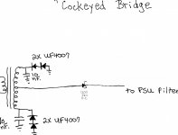
What I call a "Cockeyed Bridge" will be used for the B+ rectification scheme. It's an economical way to obtain the "zero" switching noise benefits of Schottky diodes. Actually, close examination will show the setup to be FWCT, with an "extra" diode. That "extra" diode (here a high PIV Schottky) keeps PN diode switching noise out of the PSU filter.
Take a look at the 7591 data sheet to start getting a feel for operating conditions. Ultralinear mode push/pull pairs operating in Class "AB1" will be employed.
I'm quite tired this evening and will not go into great detail.
Request Edcor to build a pair of what would be model CXPP60-6-6.6K O/P transformers, according to their numbering scheme.
Edcor's model XPWR030-220 is a tad on the hefty side, for energizing an "El Cheapo Grande", but is otherwise highly suitable. Better a bit too much power trafo than not enough.
What I call a "Cockeyed Bridge" will be used for the B+ rectification scheme. It's an economical way to obtain the "zero" switching noise benefits of Schottky diodes. Actually, close examination will show the setup to be FWCT, with an "extra" diode. That "extra" diode (here a high PIV Schottky) keeps PN diode switching noise out of the PSU filter.
Take a look at the 7591 data sheet to start getting a feel for operating conditions. Ultralinear mode push/pull pairs operating in Class "AB1" will be employed.
Attachments
Call me "chicken", but I would mount the Octal sockets on sheet metal, not FR4. Small signal circuitry on well executed PCBs is fine.
I agree with Eli regarding putting sockets on pcboards.
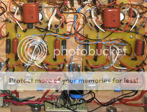
Below is one way I work around using pcboards while mounting tubes to chassis. The board is mounted over the phase splitter and output tube sockets to the underside of the chassis top plate. You can see how I added quick disconnect tabs for leads from the sockets. All "stopper" resistors are still mounted right at the tube socket pins, but the quick disconnects provide for "rolling" coupling caps and other things. The Constant Current Source for the Long Tailed Pair is on the end of the board to the right. For 7591As, we'll need a slightly larger cutout on the left pair of socket holes, or they will need to be moved out and off the board a little more to allow for space for the cathode bias resistor and capacitor. There will also need to be provision for the added grid bias connection if Eli's combo of both cathode and grid bias is used:

This early layout shows how I place the boards over the socket holes. These boards are one sided, so the copper is actually facing the chassis top when installed:

Here are the pcboards installed over the sockets The B- supply board for the CCS is at the very bottom, mounted to the front wall of the case:
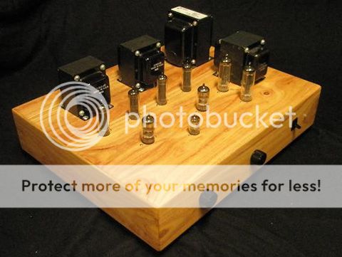
Here is the final El Cheapo with 6AQ5 finals. An El Cheapo Grande could work on this size of chassis. NOTE: I used tube rectification for no good reason except that I wanted to try it. SS rectification sounds fantastic as well. For the Grande version, I think that there is plenty of space for larger output and power transformers:
Last edited:
- Status
- This old topic is closed. If you want to reopen this topic, contact a moderator using the "Report Post" button.
- Home
- Amplifiers
- Tubes / Valves
- Somewhat Newbie..