Hi guys!
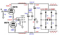
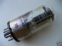
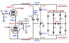
I want I building a tube buffer for my CD player with 6N7S (6N7GT) or 6N8S, under this schematics.
Please give some comments about the schematics.
thank you!
I want I building a tube buffer for my CD player with 6N7S (6N7GT) or 6N8S, under this schematics.
Please give some comments about the schematics.
thank you!
Attachments
Last edited:
Yes, yes equivalent!Gost22 means the 6SN7 (= Russian 6H8C = 6N8S)
")
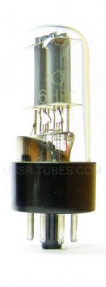
I would say that this tube/valve 6n8s (military) is better for this kind of thing!
So let's move on ...in the right direction,...
Last edited:
Yes, ~poko,~poko,...(equivalent)!Gost22 means the 6SN7 (~= Russian 6H8C = 6N8S)
6SN7~=6N8S,...understand.
Tube SOUND!?
P.S.
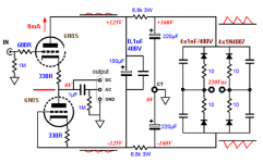
This is better (see schematics)!!
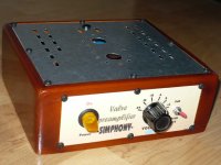
Here's the box
cheers!
Attachments
Last edited:
What's the purpose of stealing one of John Broskie's copyrighted schematics to ask the same question you've asked in about a dozen other threads?
I think you just like posting schematics and asking the same questions over and over. Erik's advice (and what others have told you again and again) is correct. Stop posting the same question and build something. Soldering irons aren't poisonous.
I think you just like posting schematics and asking the same questions over and over. Erik's advice (and what others have told you again and again) is correct. Stop posting the same question and build something. Soldering irons aren't poisonous.
Hi,let's close the topic,...
cheers!
Yes, this is a revised schematics Broskie John's!
Now I need help for connecting power supply to the heater with anode voltage catode follower?
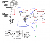
Please help me where to connect the points A and B of the heater with cathode follower? (see schematics power supply for heater)
Thank you for your cooperation!
Attachments
Last edited:
I think you can ignore the regulated PS for the moment, as it should be possible to make a line stage with AC heating.
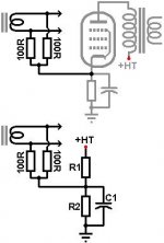
So, connect a 47k and 150k (2W) resistor in series. Put a 1000nF (electrolytic) of at least 150VDC across the 47k resistor, with the positive of the cap connected to the node between 150k and 47k. Connect the 150k loose end to B+, the 47k (and cap) to B-. Connect two 100R resistors in series across the 6,3V heater, the center of these resistors goes to the node of the 47k and 150k resistor.
Confusing description, but if you understand make a drawing and we can say if it is correct.
I think you can ignore the regulated PS for the moment, as it should be possible to make a line stage with AC heating.
So, connect a 47k and 150k (2W) resistor in series. Put a 1000nF (electrolytic) of at least 150VDC across the 47k resistor, with the positive of the cap connected to the node between 150k and 47k. Connect the 150k loose end to B+, the 47k (and cap) to B-. Connect two 100R resistors in series across the 6,3V heater, the center of these resistors goes to the node of the 47k and 150k resistor.
Confusing description, but if you understand make a drawing and we can say if it is correct.
Hi ErikdeBest!
Could you please show all this on schematics.
thank you!
Last edited:
I can't draw schematics, therefore I wrote it down so you could do it. But I did some googling and found a drawing to illustrate above. It is from valvewizard, a must read. In the attached schematic R1 should be 150k, R2 is 47k, C1 is 10muF (instead of 1000nF I wrote before). The point marked HT+ goes to the positive rail, the point marked with earth goes to the negative rail (not to earth!!)
Attachments
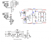
On picture is schema who is completed now you can make conection.The full schematics in peint can now a connect .
thank you!
Is this okay? (see schematics-2)
Attachments
Last edited:
Hi Gost22
Many years ago I could barely understand basic circuits and spent days to understand a small suggested modification/combination of circuits. I decided to start from the basics and built battery operated headamps, small gainclones, while reading through several books to get the understanding of circuits I have now (which is still not much, but enough not to kill myself or lose precious components).
The knowledge level you demonstrate in your posts shows you are at the same position I was years ago: besides not understanding circuit design also a lot of doubts about what sounds best, etc etc. Therefore I am not comfortable with explaining what is wrong with your circuit and to correct it: not that I don't want or can't, but I am really afraid that with your lack of knowledge you will hurt yourself with the HV present in this circuit.
My recommendation is that you do some further reading before embarking in building tube circuits. Meanwhile you may be better of building LV Solid State circuits - but take care with mains!
- Status
- This old topic is closed. If you want to reopen this topic, contact a moderator using the "Report Post" button.
- Home
- Amplifiers
- Tubes / Valves
- Catode follower with 6N7S (6n7GT)