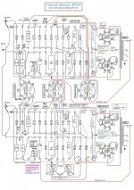
For a friend the 20 year old "Conrad Johnson MV40" beginner project has been redrawn. This amplifier DIY project uses output transformers from a sparepart "The Fisher C500" ,
......the 20 year old project used OP's with "Ultralinear solder tag's", and reached approx. 35W by 440V on the plates of EL34.
The schematic is similar to to the MV75 with some few changes. If anyone has a wish for a simple tubeamp to built, this one is a rather easy start project.
This MV45 amplifier was made with a multimeter only")
There might be some small seriel resistor value changes in the PSU to reach the right voltages on the driverboard, and if the amplifier "motorboat's" (use some old speakers for that) just increase the value of the feedback resistor (approx 1,5K) untill it stops...and then increase the potmeter a bit more and you are ready for valve sound
......the 20 year old project used OP's with "Ultralinear solder tag's", and reached approx. 35W by 440V on the plates of EL34.
The schematic is similar to to the MV75 with some few changes. If anyone has a wish for a simple tubeamp to built, this one is a rather easy start project.
This MV45 amplifier was made with a multimeter only
There might be some small seriel resistor value changes in the PSU to reach the right voltages on the driverboard, and if the amplifier "motorboat's" (use some old speakers for that) just increase the value of the feedback resistor (approx 1,5K) untill it stops...and then increase the potmeter a bit more and you are ready for valve sound
Attachments
Last edited:
Fisher 500C receivers used 7591s. EL34 family tubes are a poor mate for the O/P "iron". Fortunately, the current production ElectroHarmonix (EH) 7591 is quite decent. Be meticulous in honoring the 330 KOhm grid to ground limit, for "fixed" bias.
I know nothing about the CJ circuits mentioned. However, 7591s are easy to drive. Good small signal circuitry associated with EL84s and 6V6s works with 7591s too.
I know nothing about the CJ circuits mentioned. However, 7591s are easy to drive. Good small signal circuitry associated with EL84s and 6V6s works with 7591s too.
A quick look at the schematics showed several 1N4007 diodes. That part is a nasty, noisy, bugger. Replace the 1N4007 everywhere it's found by the much quieter UF4007.
There is a world of difference in the amount of SS switching noise produced by the 2 parts. The UF4007 is a drop in replacement for the 1N4007 that costs approx. 0.15 USD each.
Replace the 1N4007 everywhere it's found by the much quieter UF4007. There is a world of difference in the amount of SS switching noise produced by the 2 parts. The UF4007 is a drop in replacement for the 1N4007 that costs approx. 0.15 USD each.
Fisher 500C receivers used 7591s. EL34 family tubes are a poor mate for the O/P "iron". Fortunately, the current production ElectroHarmonix (EH) 7591 is quite decent. Be meticulous in honoring the 330 KOhm grid to ground limit, for "fixed" bias.
I know nothing about the CJ circuits mentioned. However, 7591s are easy to drive. Good small signal circuitry associated with EL84s and 6V6s works with 7591s too.
I have to admit that you are fast out of the box
First ...my friend got the "iron" from a Fisher 500C for test ............this is what he got!
Second ....we know that the Fisher 500C uses 7591, and that it might be necessary for him to buy better OP's.........
Third....there are about 125K from EL34 grids to ground, clearly within specs for fixed bias. see schematic....
Erlier experience showed better performance (more power) with 12BH7 as driver for a pair of EL34 (or 6550a)......he is not going to use 7591 as output valves
Regarding the 1N4007 you mentioned . You might have a point concerning the better specs from the UF4007, and I didn't know that, but there are several working quiet valveamps standing here completely silent.........using the 1N4007.........a lot of them
The noise from 1N4007 is probably measurable, but not very noticeable in a push-pull tube amplifier...I think. The situation is different in a singleend valveamp where noise and micro ac voltages is easy to detect.
....for 20 years ago the attached valveamp did "motorboat" with the 750p across the 1,5K feedback resistor. The 750p removed ...see CJ redrawing.
Attachments
Last edited:
Wouldn't you get lower distortion with a higher K (6-7K) primary OPT designed for 7591 with other tubes which usually use a bit lower (4-5K) transformers? The Heathkit W5 series I think is a good example of an extra high K primary benefits. You loose a bit of power all right, but it may work out for the better.
Wouldn't you get lower distortion with a higher K (6-7K) primary OPT designed for 7591 with other tubes which usually use a bit lower (4-5K) transformers? The Heathkit W5 series I think is a good example of an extra high K primary benefits. You loose a bit of power all right, but it may work out for the better.
Maybe you're right in that a higher Raa at 6-7K will lower distortion, but I probably should not have mentioned the two Fisher output transformers, because the intention is to use EL34 and some appropriate transformers.
To test was the Fisher op's the only available .....
The idea was....I thought that there were other DIY people who would amuse themselves by building the Conrad johnson MV40 circuit , because I had a good experience with this extremely well sounding tube amp.
The "best" tweak to Mullard style circuitry is to put a CCS in the LTP's tail instead of that blasted resistor. Force symmetry between the 2 sides of the differential gain block.
Perhaps the finest implementation of Mullard topology, ever, is the H/K Cit. 5. It uses the 12BY7 as the voltage amplifier. High gm is your friend, in designs with loop NFB. Soviet surplus 6П3С-Е (6p3s-e) stock will drop right into the Cit. 5. setup, with zero parts value changes. The Fisher O/P "iron" mates perfectly with 6L6 family tubes. As long as the power handling capability of the transformers is not exceeded, you will do fine.
Perhaps the finest implementation of Mullard topology, ever, is the H/K Cit. 5. It uses the 12BY7 as the voltage amplifier. High gm is your friend, in designs with loop NFB. Soviet surplus 6П3С-Е (6p3s-e) stock will drop right into the Cit. 5. setup, with zero parts value changes. The Fisher O/P "iron" mates perfectly with 6L6 family tubes. As long as the power handling capability of the transformers is not exceeded, you will do fine.
Attachments
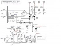
Conrad Johnson PSU modified for high voltage transformer
In order to use my friends powertransformer which was available for the DIY amplifier, the PSU has been changed a bit.
The Vac / DC outlet was a bit too high for the OP's and the 6L6GC's
......some resistor values may have to adjusted to get the right voltages....that's DIYhttps://picasaweb.google.com/vbkolsen/ConradJohnsonMV75ModifiedToMV40#5872342485854179250
In order to use my friends powertransformer which was available for the DIY amplifier, the PSU has been changed a bit.
The Vac / DC outlet was a bit too high for the OP's and the 6L6GC's
......some resistor values may have to adjusted to get the right voltages....that's DIY
https://picasaweb.google.com/vbkolsen/ConradJohnsonMV75ModifiedToMV40#5872342485854179250In order to use my friends powertransformer which was available for the DIY amplifier, the PSU has been changed a bit.
The Vac / DC outlet was a bit too high for the OP's and the 6L6GC's
......some resistor values may have to adjusted to get the right voltages....that's DIY
Change of website information:
The company "Webbyen.dk" closes at the end of 2014.
The hobbysite http://www.tubeamp.hobbysider.dk/
will not continue .
Please find a copy-page at Google Sites:
https://sites.google.com/site/httpstubeamp/
The website is under construction
Last edited:
- Status
- This old topic is closed. If you want to reopen this topic, contact a moderator using the "Report Post" button.
- Home
- Amplifiers
- Tubes / Valves
- Conrad Johnson MV40 copy and Fisher OP's