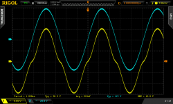
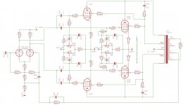
Today, I've wired together my first tube power amp. a bit nerve wrecking I might add  . Two KT88's PP (for now, will be four later on) driven by a ECC99 PI into a Hammond 1650T in ultra linear mode. Attached image is the result into a 4 ohm resistive load. There's no global feedback at the moment and bias is set to -60V. B+ is 410 volts. I'm still a noob, but can't imagine the crossover distortion measured to be normal! The signal going into the KT88s is fine (blue line). What's the reason for this distortion? No feedback? Bias to low? It's a learning experience so any help is welcomed. Thanks.


That there is cross-over distortion, Dr. Funkenstein.
That's one of the chief reasons we have negative feedback in amplifier design of the push-pull PP type. It is a "gain vampire", stealing many dB of gain (necessarily, and irreducibly), but the consequence is that the output gets all nice-n-cleaned-up.
You also might be biasing too low ... you've got the output tubes working very near cut-off. That aggravates the cross-over distortion curve. So obviously ... you need to "do" at least 1 thing right away (which is "cheap", taking little-to-no work to do).
That would be, to send all us EE/AF types a nice diagram/schematic ... then let us make very specific recommendations as to what to try after that!
Thank me later. GoatGuy
Folks will usually include a 10 Ohm resistor in the series with each cathode to use as a current test point. A typical 35mA for example will cause 0.35 Volts across each resistor. You'll need a way to adjust bias because all valves are different, enough to matter.
All good fortune,
Chris
All good fortune,
Chris
Since you use only half of the number of KT88's, you have to double the resistive load. So 8 ohm on the 4 ohm tap, or 16 ohm on the 8 ohm tap. If you leave out output valves without changing the load, the valves will see an impedance that is too low. Simplified, with signal applied this would ask more current (and dissipation) from the KT88's than what this design calls for. This will also increase cross over distortion.
If your B+ really is about 400 Volts, you'll be safe at idle currents of 60mA or even higher, up to maybe 80mA with good valves. OTOH you may likely find that sound doesn't improve above some lower bias, even 30 to 40 mA. You'll really want to experiment.
All good fortune,
Chris
All good fortune,
Chris
Distortion be gone! 
Thanks for all input. I've yet again learned alot from you guys. I raised the bias from 60 to around 50 volts (I still need to implement the 10 ohm cathode resistor). The distortion was almost gone, but still a tiny bit present. Next was the implementation of the second set of tubes (since I didn't have an 8 ohm dummy load yet, as per parafeeds suggestion) and I've now got a beautiful sinus without any visible crossover distortion! Without the GNFB I might add. I now feel I've got a good base on which I can experiment further with feedback, zobel networks for the transformer, etc.

Thanks for all input. I've yet again learned alot from you guys. I raised the bias from 60 to around 50 volts (I still need to implement the 10 ohm cathode resistor). The distortion was almost gone, but still a tiny bit present. Next was the implementation of the second set of tubes (since I didn't have an 8 ohm dummy load yet, as per parafeeds suggestion) and I've now got a beautiful sinus without any visible crossover distortion! Without the GNFB I might add. I now feel I've got a good base on which I can experiment further with feedback, zobel networks for the transformer, etc.

Last edited:
- Status
- This old topic is closed. If you want to reopen this topic, contact a moderator using the "Report Post" button.
- Home
- Amplifiers
- Tubes / Valves
- First power amp build. Is this normal??
