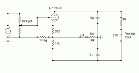
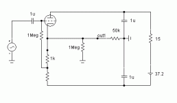
Excuse me Frank, I have not understood
I have a 250 V supply and the anode to catode voltage
difference is about 125V with about 8/8.5 mA.
Again, the circuit is not DC coupled.
There are the two escape capacitors.
Note that despite their value is 1 uF, they
act as they are about 30 uF (mu times),
and this is one of the reason to prefer this
circuit ( as for me , obviously).
grazie e ciao
Federico
Ciao,
Don't you say your PS is floating? It says 250V, so I think it is +/- 250V, the + goes to the anode of the tube, the - to the cathode?
That's voltage drop across anode and cathode.
Aren't they referenced to ground?
As capacitance multipliers?
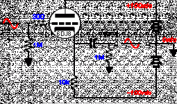
I haven't seen anything like it before but it looks like this one:
Maybe it's just me not understanding your circuit, in which case I apologise.
Cheers,
I have a 250 V supply and the anode to catode voltage
Don't you say your PS is floating? It says 250V, so I think it is +/- 250V, the + goes to the anode of the tube, the - to the cathode?
the anode to catode voltage difference is about 125V with about 8/8.5 mA.
That's voltage drop across anode and cathode.
Again, the circuit is not DC coupled.
Aren't they referenced to ground?
Note that despite their value is 1 uF, they act as they are about 30 uF (mu times), and this is one of the reason to prefer this circuit ( as for me , obviously).
As capacitance multipliers?
I haven't seen anything like it before but it looks like this one:
Maybe it's just me not understanding your circuit, in which case I apologise.
Cheers,
Attachments
No Frank,
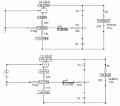
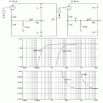
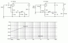
the two circuits are different in various ways, for example the different position of the capacitors. Look at frequency response
that follows. The –3db frequencies are very different,
the ratio being about 18 that is mu/2.
With this arrangement we can use smaller caps of high quality.
Otherwise, with equal caps we have more extension at the low freqs.
The point, however, is not the extension of the frequency response, but the output resistance behavior at low freq.
as you can see.
Ciao
federico
Attachments
Hi,
Yes, not that it matters.
Have you actually built it?
How about DC offset at the output?
I usualy don't count on miracles if it's critical.
Which caps?
One circuit is DC coupled at first look but isn't really, the other isn't at all and you have 0.200µF working into slightly less than 50K. (1M//50K)
Which goes some way to explain the roll-of in the bass department.
Enlighten me because wherever I see differences and vice versa you seem not to.
No offense, just trying to understand what I don't see.
Cheers,
the two circuits are different in various ways, for example the different position of the capacitors.
Yes, not that it matters.
Have you actually built it?
How about DC offset at the output?
I usualy don't count on miracles if it's critical.
Otherwise, with equal caps we have more extension at the low freqs.
Which caps?
One circuit is DC coupled at first look but isn't really, the other isn't at all and you have 0.200µF working into slightly less than 50K. (1M//50K)
Which goes some way to explain the roll-of in the bass department.
Enlighten me because wherever I see differences and vice versa you seem not to.
No offense, just trying to understand what I don't see.
Cheers,
Hi Frank,
First of all I have to apologize for my bad knowledge
of English language.
There is no DC offset at the output if there is no
grid current. That is, if the supply provides a
voltage sufficiently high and the tube is properly biased
there are no problems.
However if one, for instance, uses batteries and works
with a voltagesupply smaller than, say, 60 Volts,
grid current is likely to appears since we have small polarization.
In this case we have an offset at the output and
we have to modify the circuit as reported.
That is, we have to put a cap at the input.
Again, with this last arrangement there is
absolutely no DC offset at the output.
(Automatically, no manually adjustment required)
I am experimenting at low voltage (actually
about 37V supply) with ECC88, E88CC, PCC88
but I had the best results with ECC86.
Regarding the caps., I simply want to say that
if I have at my disposal two 0.1uF caps I’ll
use them in the proposed circuit rather than
in a cathode follower because of the better
performance, with particular reference to the
output impedance.
Bye
Federico
Attachments
Ciao, Federico, the idea is nice. I don’t see any necessity to connect both earths together – so you will get galvanic decoupling between the source (e.g. cd player) and the load (amp), not counting 1M resistor. That is good. I have several questions:
What if the output caps aren’t be equal?
As I presume you will connect the chassis to the input earth. How about simulation with two parasitic capacitance from both supply rail to that point?
What if the output caps aren’t be equal?
As I presume you will connect the chassis to the input earth. How about simulation with two parasitic capacitance from both supply rail to that point?
Federico, I’ve checked your simulations with ucap and sorry to discover that your PSRR data is doubtful.  I got -45dB for your circuit values.
It is a bridge: left upper branch – internal triode resistance Ri; left bottom branch – 13.8kOhm. For the bridge null the capacitors must be in proportion Ri/13.8kOhm. Ri for 6DJ8 ~2.7kOhm. For the ucap model for 6DJ8 the max PSRR will be around 0.34u (upper cap value)
It is a bridge: left upper branch – internal triode resistance Ri; left bottom branch – 13.8kOhm. For the bridge null the capacitors must be in proportion Ri/13.8kOhm. Ri for 6DJ8 ~2.7kOhm. For the ucap model for 6DJ8 the max PSRR will be around 0.34u (upper cap value)
Hi Dimitri, some interesting points here.
As you have underlined it is a bridge.
But, in your calculation you have probably forgot
the bias resistance whose value (300 Ohm)
has to be multiplied (1+mu) times
and added to the internal triode resistance.
In my example we have ri= 3254 ohm
mu= 34.285 that is
[ri + (1+mu)*300]= 13840 ohm.
Really, the exact value of the above parameters
are not so critical since, as you have suspected,
differences in the output caps will destroy the balance.
The Rk resistor (13.8k) has to be a pot. So,
if PSSR minimization is the target, one
can adjust its value as a function of the working
point ( on which ri and mu depends) and of
the caps value.
For instance if I change the value of the upper cap
to .47u ( instead of .5u) the PSSR shifts from –88db
to –61 db and I have to put Rk=13k ohm to restore
the original pssr value. On the other hand if I change
the lower cap to .47u I have to make Rk=14.7k
to balance the bridge.
The small resistance in series to the supply
is for lower PSSR at high freq.
Parasitic capacitance from both supply rails
to earth does not imbalance the bridge if they
are of the order of hundreds picoF.
Thanks for your comments Dimitri.
Bye
Federico
- Status
- This old topic is closed. If you want to reopen this topic, contact a moderator using the "Report Post" button.
- Home
- Amplifiers
- Tubes / Valves
- simple line buffer
