Hi folks,
I've been looking for a clear description of the heater-cathode leakage test, but I have not been able to find a detailed one...
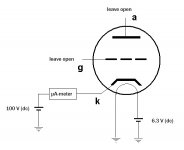
If I am not mistaking, heater-cathode leakage happens when a hot heater emits electrons to the cathode when the heater is more negative than the cathode. I would like to use only DC voltages for this test. So could it be useful to perform this test with anode and grid disconnected, the heater connected to 6.3V dc and the cathode connected to a high positive dc voltage, and then measuring the current at the cathode side? I am wondering if this simple setup could do the trick for e.g. a 12AX7 tube..
To clarify what I mean, I added a drawing to this post!
I am looking forward to your comments,
Lebowski
I've been looking for a clear description of the heater-cathode leakage test, but I have not been able to find a detailed one...
If I am not mistaking, heater-cathode leakage happens when a hot heater emits electrons to the cathode when the heater is more negative than the cathode. I would like to use only DC voltages for this test. So could it be useful to perform this test with anode and grid disconnected, the heater connected to 6.3V dc and the cathode connected to a high positive dc voltage, and then measuring the current at the cathode side? I am wondering if this simple setup could do the trick for e.g. a 12AX7 tube..
To clarify what I mean, I added a drawing to this post!
I am looking forward to your comments,
Lebowski
Attachments
That would work to measure insulation resistance (a DC parameter), but does not address the capacitance (an AC parameter). Oftentimes this leakage exhibits itself as hum injected into the signal, which is objectionable. AC signal is able to transport across both insulation resistance as well as capacitance, so I would think you will want to measure both.
Hi folks,
I've been looking for a clear description of the heater-cathode leakage test, but I have not been able to find a detailed one...
If I am not mistaking, heater-cathode leakage happens when a hot heater emits electrons to the cathode when the heater is more negative than the cathode.
Not exactly so. Heater/cathode leakage involves two different processes. Even though aluminum oxide is both refractory and an excellent insulator at room temp, at red heat it becomes a slightly N-type semiconductor. Put that in contact with metal (nickle cathode sleeve) and you make an incidental diode. If forward biased, it can leak some heater voltage to the cathode. This isn't a big deal if the cathode is at AC ground, but may become problematic when it isn't, as in cathode followers, cascodes, SRPPs, Mu followers. Then, some DC on the heater(s) to keep that incidental diode reverse biased might prove helpful.
The other source of HK leakage is capacitance. This is seldom an issue until you're into VHF ranges. Then, you need to decouple the heater with a suitable RF choke, otherwise, you bypass all your input to ground through the heater supply.
I would like to use only DC voltages for this test. So could it be useful to perform this test with anode and grid disconnected, the heater connected to 6.3V dc and the cathode connected to a high positive dc voltage, and then measuring the current at the cathode side? I am wondering if this simple setup could do the trick for e.g. a 12AX7 tube..
To clarify what I mean, I added a drawing to this post!
I am looking forward to your comments,
Lebowski
You have to be careful of the "high positive DC voltage". Keep in mind the Vhk spec, and don't bust it, otherwise, your "test" ruins the DUT. You could accomplish the same thing by using a resistance/impedance meter intended for measuring high impedances, i.e. a "Megger". Do be sure it doesn't use enough sense voltage to exceed the Vhk spec.
You could also possibly add an AC test, but that's not really necessary if you're not doing VHF designs.
Lebowski, did you check some previous posts, such as,
http://www.diyaudio.com/forums/tubes-valves/205710-ac-heater-reference-b.html
http://www.diyaudio.com/forums/tubes-valves/205710-ac-heater-reference-b.html
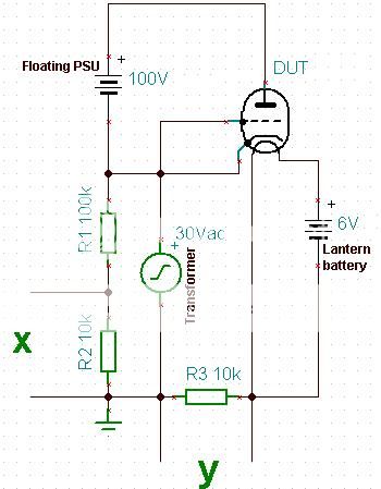
This method will measure leakage resistance of hundreds of megohms using the X/Y inputs of an oscilloscope. The transformer applies the voltage between h and k, and could have any value you like.Hi folks,
I've been looking for a clear description of the heater-cathode leakage test, but I have not been able to find a detailed one...
The X input plots the voltage applied between h and k (attenuated by R1-R2) and the Y input plots the voltage produced across R3 by the leakage current (1mV = 100nA leakage)
However, most valves actually have extraordinarily high leakage resistance, so don't expect to see much unless you have a poor valve!
Thanks for your replies!!
I want to do this measurement for the 12A*7 family, used in an audio equipment repair shop. They will not be used for VHF. So I guess the problems that could occur with h-c leakage in audio equipment would be related to the insulation between heater and cathode that behaves like a incidental diode, and thus allowing a small current to flow between H and C.
So would it be necessary in that case to perform the test with AC between heater and cathode? Wouldn't a DC voltage between heater and cathode give me the same information?
Secondly -and this might be a really stupid question- , if I am only performing this test, is it necessary to apply an anode voltage and a grid voltage? Can't I just measure the leakage current by only making the heater more negative than the cathode?
With kind regards,
Lebowski
Merlin's test jig applies AC to allow the oscilloscope to sweep through a wide range of "DC" voltages without having to take separate measurements.
As the resistance of most tubes is extremely high, the measurement is difficult to make with any form of resolution. For example, 1000 Megohm means 10V and 10nA, which will show up as 0.1mV signal level (if that can be discerned on your oscilloscope!!) - and that is likely to be a poor valve's level, with most typical 12A.7 valves likely to measure a higher resistance at 10V applied level.
Are you just looking to test for bad-failed insulation, as that application does not per se need exotic resolution and so would show up more easily, either with an oscilloscope or a meter type test jig.
- Status
- This old topic is closed. If you want to reopen this topic, contact a moderator using the "Report Post" button.
- Home
- Amplifiers
- Tubes / Valves
- Heater-Cathode Leakage