I've attached the Vf vs If curve as measured from a working part off a Fisher 500C for the benefit of those interested in replacing the original with a silicon diode.
To the mods, if this is not the right place please move it to the appropriate location. I reckon it should be in the tubes area since no modern design incorporates selenium rectifiers
To the mods, if this is not the right place please move it to the appropriate location. I reckon it should be in the tubes area since no modern design incorporates selenium rectifiers
Attachments
Actually I just tickled the X and Y values out of the graph to figure slope & intercept. (and therefore, forward cutoff voltage and equivalent series resistor value). Magic of EXCEL, and taking the two visually different segments
Vf = 0.51, Req = 7.3 ohm ... and then the second part in parallel:
Vf = 1.14, Req = 9.3 ohm ... in parallel with the first one.
HOWEVER, that being said ... there are a couple oddities in play: one is the forward voltage of 2.5 ... has a current-flow of 0.42 amps. My recollection of selenium-stack rectifiers was that each section (plate) is only good for like 20 volts reverse or something like that. Since they're technically a kind of Schottky, forward voltage drop can be low. How many plates though does this unit have?
As I found, there really isn't an exact silicon replacement. Pretty close is a standard silicon rectifier in series with a 7 ohm resistor, and from the diode-resistor point, another silicon rectifier with a 9 ohm resistor "across" the first resistor. Simple, and will have similar I:V characteristics. Just a bit higher shift in the forward conduction voltage, is all.
GoatGuy
[I researched CREE high-voltage Schottky SiC rectifiers... but they have a 1.5V drop or higher. Not much of a Schottky! And the silicon high-PIV diodes/rectifiers also seem to have the higher 1.4-1.8V forward voltage drop ... i guess 'cuz they put two lower-voltage rectifiers in series... (? anyone know ?) ... and there are no high-voltage germanium parts, and low-volt-drop conventional Schottky's also have depressingly low reverse breakdown voltage. So... I think the 'just use silicon' answer remains the best]
Last edited:
Hitachi-nut: Selenium rectifiers deteriorate with age;
your curves bend in the "wrong" direction, and there is that "knee" in the middle - both indicating your specimen is no longer in its original condition;
these flat Siemens had spring loaded plates or pills inside, and if they became loose over time, it may look like yours ...
max voltage for Se was 18Vrms per plate, so B30C600 had 2 pills per branch, total of 8.
voltage drop for Se was usually 1V at indicated max current (actually lower than Si).
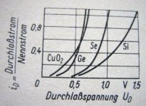
Diodes for Selenium
that's from one OLD textbook! Out of curiosity... I moused over to Fairchild's site, to see what the good ol' 1N4146 forward voltage drop was ... what a well behaved chunk of silicon sand! 0.7V at 5 ma. I think now that the recommendation I made above stands. Either use the small-value resistors in series with the replacement silicon rectifier to simulate a softer switching curve, or if there's sufficient filtering in C(L/R)C stages ... then dispense with it. Having a small value resistor though does substantially damp the peak amperage that will flow, thus much extending the life of the replacement diodes.
GoatGuy
from textbook
that's from one OLD textbook! Out of curiosity... I moused over to Fairchild's site, to see what the good ol' 1N4146 forward voltage drop was ... what a well behaved chunk of silicon sand! 0.7V at 5 ma. I think now that the recommendation I made above stands. Either use the small-value resistors in series with the replacement silicon rectifier to simulate a softer switching curve, or if there's sufficient filtering in C(L/R)C stages ... then dispense with it. Having a small value resistor though does substantially damp the peak amperage that will flow, thus much extending the life of the replacement diodes.
GoatGuy
I deliberately picked one from the time when these Se rectifiers were produced - I think that was the topic.
yes your Si diode is .7v@5mA and 1v@rated max dc current (100,200mA) and that is what my curves show, the vertical axis is standardised to max dcrating =1.
And Si max is rated @175 oC whereas Se max was rated @just 40 oC - hence the large cooling fins - or the flat Siemens which had to be bolted to the chassis when operated any near the rated current
and if we consider, that B30C600 is 30vrms and C600 means cap loaded 600mAdc, we have to take into account that peak current is maybe 10x or more for c-load, we talk of 1n4001 rather than 1n4146 and peak current 10A maybe ... where a 1n4001 has 1,5v forward drop, so ...
anyway, series R helps control inrush current and switching noise which is much higher w/Si than w/Se. Se behaved very soft in that it had no sharp threshold - no need for snubbers.
So... then... do it, it sounds like.
A 1 amp 1N400X (x=1..7) any of which would be OK. The insertion of a 4 ohm progressive V(forward) response resistor (snubber) is also a good measure, and simulates the overall "brand new selenium" rectifier response. Even if the average is 1 amp I²R is only 4 watts. EI on the 1N4001 rectifier runs about 1 watt, which a bit above its max rating, isn't it? Maybe not.
GoatGuy
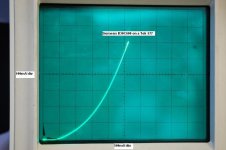
OK. I have attached an updated plot, this time with the axis swapped and used a different free CSV to graph program, not M$ Excel. I have also the characteristic curve of one of the bridge legs using my Tek 577. The axes units and scaling are very close making comparison easier.
I forgot to add on the original post that the plot was the average values of the 4 legs, hence the kink on the curve.
I forgot to add on the original post that the plot was the average values of the 4 legs, hence the kink on the curve.
The peculiar axes (bilinear current, and opposite way round to the normal convention) hide the fact that this appears to be not much different from a pair of silicon diodes in series.
Useful data, though.
Attachments
Calculate number of elements in the rectifier, and put as many silicon diodes on series. Add some resistors in series. Then add rotten sour cabbage, and put it all in the plastic bag.
Hmmm... Voltage drop, resistance, smell... What else?
Smoke, I forgot smoke!
Rotten sour cabbage smell have to be accompanied by smoke, so some source of smoke have to be added. Celluloid may be?
Hmmm... Voltage drop, resistance, smell... What else?
Smoke, I forgot smoke!
Rotten sour cabbage smell have to be accompanied by smoke, so some source of smoke have to be added. Celluloid may be?
Blimey! I am so in awe of you people in being able to understand all that.yes your Si diode is .7v@5mA and 1v@rated max dc current (100,200mA) and that is what my curves show, the vertical axis is standardised to max dcrating =1.
And Si max is rated @175 oC whereas Se max was rated @just 40 oC - hence the large cooling fins - or the flat Siemens which had to be bolted to the chassis when operated any near the rated current
and if we consider, that B30C600 is 30vrms and C600 means cap loaded 600mAdc, we have to take into account that peak current is maybe 10x or more for c-load, we talk of 1n4001 rather than 1n4146 and peak current 10A maybe ... where a 1n4001 has 1,5v forward drop, so ...
anyway, series R helps control inrush current and switching noise which is much higher w/Si than w/Se. Se behaved very soft in that it had no sharp threshold - no need for snubbers.
I have a Revox Model 40 amp which I have just pulled out of our wardrobe where it has been for about 25 years. It has one of these rectifiers in the power supply and I need to replace it. In everyday terms that a simple lad from Lancashire can understand, what do I replace it with please?
Ian.
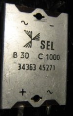
I found this flat Selenium rectifier from SEL (Standard Electric Lorenz) in my junk box
B30C1000 quite similar to the OPs.
Here's some raw data and comparison with modern Si. If someone wants to compile a plot pls be welcome to do so.
B30C1000 Se Bridge SEL flat pack 30Vrms/1A Ifav C-Load
KBU4D Si Bridge 150Vrms/4A
1N4002 Si Diode 100Vrrm/1A
1N5402 Si Diode 100Vrrm/3A
---------------------------------------------
Idc[mA]...B30C1000...KBU4D...1N4002...1N5402
---------------------------------------------
..50........0.39..........0.69.......0.78......0.72 V
.100.......0.45
.200.......0.53
.250.......0.61..........0.73.......0.81......0.76 V
.300.......0.64
.400.......0.71
.500.......0.76..........0.77.......0.83......0.78 V
.600.......0.80
.700.......0.84
.800.......0.90
.900.......0.94.........0.79.......0.85.......0.80 V
---------------------------------------------
up to 50% rated load Selenium has actually lower voltage drop than Si
and even above it does not loose much.
So for the low voltage 30V device it seems feasable to just drop in a properly rated Silicon bridge for a Se rectifier. Series resistors may only be helpful close to max load. And if the designer choose 50% max load Si seems to be right on spot.
The situation is quite different for the higher voltage parts where Se has to use multiple junctions in a stack.
I happened to also have a E250C50 Selenium half wave rectifier 250Vrms/50mA.
There may be anything between 10 and 15 plates in series.
and here's the data:
------------------
Idc[mA]...E250C50
------------------
..10.........8.1 V
..20.......10.2 V
..30.......11.9 V
..40.......13.6 V
..50.......15.4 V
------------------
A Si 1N4007 of course would still be around 0.7V.
Still - does it really matter whether B+ is 200V with Selenium and 212V with Silicon ?
Maybe not if it wasn't for control of inrush current or HF noise which is definitely worse in Silicon. Of course one could also place 15 Si diodes in series, a penny a piece.
Attachments
Last edited:
Hmmm... Voltage drop, resistance, smell... What else?
Smoke, I forgot smoke!
you forgot a pinch of rat poison ...
Selenium is toxic, but trace amounts are necessary for cellular function ...
PayLoadDE:
millamp volts V-intercept R=E/I
10 8.1 1.66 166
20 10.2 3.76 188
30 11.9 5.46 182
40 13.6 7.16 179
50 15.4 8.96 179.2
slope 0.18 mean R: 178.84
intercept 6.44
So... 8 1N4003's in series, with a 180 ohm, 5 watt resistor in series with that. Almost perfectly modelled selenium HV behavior.
GoatGuy
millamp volts V-intercept R=E/I
10 8.1 1.66 166
20 10.2 3.76 188
30 11.9 5.46 182
40 13.6 7.16 179
50 15.4 8.96 179.2
slope 0.18 mean R: 178.84
intercept 6.44
So... 8 1N4003's in series, with a 180 ohm, 5 watt resistor in series with that. Almost perfectly modelled selenium HV behavior.
GoatGuy
- Status
- This old topic is closed. If you want to reopen this topic, contact a moderator using the "Report Post" button.
- Home
- Amplifiers
- Tubes / Valves
- Siemens B30C600 selenium bridge rectifier