You can never get the Vfk within the max. 90V specs for the upper and lower triode at the same time.One cathode almost Gnd level and the other near 200V is to much.
Max.distance is 2x90V !
A solution could be separate tubes for up and down with the upper two (other channel) a heatersource of it's own,200V above Gnd.
Or another tube
Mona
Max.distance is 2x90V !
A solution could be separate tubes for up and down with the upper two (other channel) a heatersource of it's own,200V above Gnd.
Or another tube
Mona
quote from Valve Wizard
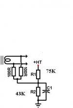
Heater elevation: Because the upper cathode is at a high voltage it is usually necessary to elevate the heater supply to avoid exceeding the maximum rated heater-cathode voltage (Vhk). For the ECC81 this is 90V, so we would need to elevate the heater by at least 100V.
I have no idea what it means, but thats what it says
only found the figures to look different
or are you saying your measured heater-cathode voltage is 76V, and ok being below 90V
Using 100V to elevate the heater like the attached schematic, I measure:
Plate lower triode
Right 137,4V
Left 135,5V
Replace the red LED by the 470R and 22µ in one channel as shown in the first schematic for testing purposes. Check voltages again afterwards.
Rundmaus
EDIT: If everything else seems ok, the LED bias scheme is the only difference to the schematic with its design voltages. Change back the bias scheme to see if the problem occurs from that.
Rundmaus
EDIT: If everything else seems ok, the LED bias scheme is the only difference to the schematic with its design voltages. Change back the bias scheme to see if the problem occurs from that.
Last edited:
You can never get the Vfk within the max. 90V specs for the upper and lower triode at the same time.One cathode almost Gnd level and the other near 200V is to much.
Max.distance is 2x90V !
A solution could be separate tubes for up and down with the upper two (other channel) a heatersource of it's own,200V above Gnd.
Or another tube
Mona
With other tube the same measurement.
Replace the red LED by the 470R and 22µ in one channel as shown in the first schematic for testing purposes. Check voltages again afterwards.
Rundmaus
Lower plate 103.7V
So have I to come back to cathode RC in place of LED?
Not sure about that. I'd have to pull my Morgan Jones copy from below a large stack of physics stuff and read up on mu follower design.
Though I am able to do some fault finding by logical and general circuit design and measurement principles, I have no experience in designing mu followers.
Maybe some of the tube forum masters of old can cut in here?
Rundmaus
I make following The Valve Wizard web link: The Valve Wizard -Mu Follower
Still hum with the input shorted to ground?
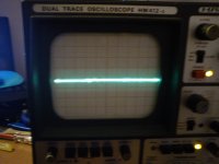
The scope trace is blurred... 0.5us sounds very short. 'Hum' usually is something in the 50-100Hz range, meaning approx. 20ms to 10ms in period length.
If you have a scope available, step one would be to measure the hum you're experiencing. The frequency would surely give hints about the hum source!
- Status
- This old topic is closed. If you want to reopen this topic, contact a moderator using the "Report Post" button.
- Home
- Amplifiers
- Tubes / Valves
- ECC81 mu-follower problem