PS - late come here - but what the heck.
NOTES from reading the whole darn thread...
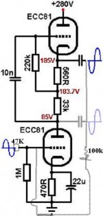
[1] You should use a pair of silicon rectifiers in series (0.7v ea, nominal forward voltage drop) instead of a 1.8 volt LED. This will cause higher quiescent current flow.
[2] The value of the 33K resistor can be changed to adjust plate of lower triode, easily. Remember E = I R (volts = current times resistance). If your plate (lower triode) is say 100 volts, and the voltage across the 33K resistor is 70 volts (picking arbitrary numbers - you have to measure yours!) then a quick approximation is 100 (what plate is) minus 85 (what you want) = 15 volts more drop. Voltage across 33K is 70, there I = E/R = 70/33 = 2.12 milliamps. You need another 15... so R = E/I = 15/2 = 7.5K more. Nice thing - since you mod your own circuit - either just put another resistor in series with the 33K, or (what I like!) a 25K trim potentiometer. Then you just adjust it while running, and keep measuring the plate. When it is at the desired voltage, turn the whole thing off, and without taking the Pot out, just measure the combined resistance of the 33K + pot. Whatever that is... choose a standard resistor that reasonably closely matches. Take both 33K out and pot, and replace with the fixed R.
That is all for now -GoatGuy-
NOTES from reading the whole darn thread...
[1] You should use a pair of silicon rectifiers in series (0.7v ea, nominal forward voltage drop) instead of a 1.8 volt LED. This will cause higher quiescent current flow.
[2] The value of the 33K resistor can be changed to adjust plate of lower triode, easily. Remember E = I R (volts = current times resistance). If your plate (lower triode) is say 100 volts, and the voltage across the 33K resistor is 70 volts (picking arbitrary numbers - you have to measure yours!) then a quick approximation is 100 (what plate is) minus 85 (what you want) = 15 volts more drop. Voltage across 33K is 70, there I = E/R = 70/33 = 2.12 milliamps. You need another 15... so R = E/I = 15/2 = 7.5K more. Nice thing - since you mod your own circuit - either just put another resistor in series with the 33K, or (what I like!) a 25K trim potentiometer. Then you just adjust it while running, and keep measuring the plate. When it is at the desired voltage, turn the whole thing off, and without taking the Pot out, just measure the combined resistance of the 33K + pot. Whatever that is... choose a standard resistor that reasonably closely matches. Take both 33K out and pot, and replace with the fixed R.
That is all for now -GoatGuy-
PS - late come here - but what the heck.
NOTES from reading the whole darn thread...
[1] You should use a pair of silicon rectifiers in series (0.7v ea, nominal forward voltage drop) instead of a 1.8 volt LED. This will cause higher quiescent current flow.
[2] The value of the 33K resistor can be changed to adjust plate of lower triode, easily. Remember E = I R (volts = current times resistance). If your plate (lower triode) is say 100 volts, and the voltage across the 33K resistor is 70 volts (picking arbitrary numbers - you have to measure yours!) then a quick approximation is 100 (what plate is) minus 85 (what you want) = 15 volts more drop. Voltage across 33K is 70, there I = E/R = 70/33 = 2.12 milliamps. You need another 15... so R = E/I = 15/2 = 7.5K more. Nice thing - since you mod your own circuit - either just put another resistor in series with the 33K, or (what I like!) a 25K trim potentiometer. Then you just adjust it while running, and keep measuring the plate. When it is at the desired voltage, turn the whole thing off, and without taking the Pot out, just measure the combined resistance of the 33K + pot. Whatever that is... choose a standard resistor that reasonably closely matches. Take both 33K out and pot, and replace with the fixed R.
That is all for now -GoatGuy-
Can I use one single rectifier 1,5V@10A like this: silicon rectifier?
PS - late come here - but what the heck.
NOTES from reading the whole darn thread...
[1] You should use a pair of silicon rectifiers in series (0.7v ea, nominal forward voltage drop) instead of a 1.8 volt LED. This will cause higher quiescent current flow.
[2] The value of the 33K resistor can be changed to adjust plate of lower triode, easily. Remember E = I R (volts = current times resistance). If your plate (lower triode) is say 100 volts, and the voltage across the 33K resistor is 70 volts (picking arbitrary numbers - you have to measure yours!) then a quick approximation is 100 (what plate is) minus 85 (what you want) = 15 volts more drop. Voltage across 33K is 70, there I = E/R = 70/33 = 2.12 milliamps. You need another 15... so R = E/I = 15/2 = 7.5K more. Nice thing - since you mod your own circuit - either just put another resistor in series with the 33K, or (what I like!) a 25K trim potentiometer. Then you just adjust it while running, and keep measuring the plate. When it is at the desired voltage, turn the whole thing off, and without taking the Pot out, just measure the combined resistance of the 33K + pot. Whatever that is... choose a standard resistor that reasonably closely matches. Take both 33K out and pot, and replace with the fixed R.
That is all for now -GoatGuy-
I ended left channel 60K1 & right channel 63K2
")
OK, now use 1N914 or 1N4448 type diodes.
ALSO (rather important) do not think that setting the left channel at 60K and the right channel at 63K is the "right solution" (i.e. independent resistance values, chosen to get the front-end triodes at the same operating point). The problem is that the amplification factor is highly dependent on those 60/63K resistors. Hence... if they're different values, you're going to have different amplification per channel.
Now wait ... it gets better - the amplification might actually be the same, or even inverted (the one with the higher resistance, expected to have more gain, actually has less). This is because of basically "huge variation in tubes". They're really quite different, unless very well matched.
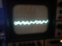
So in the end, if I was doing this, I'd leave the little adjustment trimpots in place, and adjust the output using your oscilloscope in the A-B mode (where one signal is subtracted from the other). Feed a nice 100 millivolt input into both channels, then fiddle with one of the trimpots until basically the signal is best nulled out. That's as good as you're going to get for matching the gain of the different tubes.
GoatGuy
ALSO (rather important) do not think that setting the left channel at 60K and the right channel at 63K is the "right solution" (i.e. independent resistance values, chosen to get the front-end triodes at the same operating point). The problem is that the amplification factor is highly dependent on those 60/63K resistors. Hence... if they're different values, you're going to have different amplification per channel.
Now wait ... it gets better - the amplification might actually be the same, or even inverted (the one with the higher resistance, expected to have more gain, actually has less). This is because of basically "huge variation in tubes". They're really quite different, unless very well matched.
So in the end, if I was doing this, I'd leave the little adjustment trimpots in place, and adjust the output using your oscilloscope in the A-B mode (where one signal is subtracted from the other). Feed a nice 100 millivolt input into both channels, then fiddle with one of the trimpots until basically the signal is best nulled out. That's as good as you're going to get for matching the gain of the different tubes.
GoatGuy
Like a big hum, yes I'm sure I have other line amp, tomorrow I will try with other power transformer.
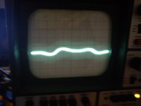
To avoid hum noise finally ended changing the transformer.
Gain is X 58.8 so I want to raise the gain adding NFB to a total of max. 20-25dBs in place of using a voltage divider at the input so using NFB lowers distortions & output impedance. Can be implemented. 100K from output cap to grid of lower tube and 47K in series with input cap?
Attachments
Only X2 = 6dBs is too low, how can calculate to change the values to get 20-25dBs?
Gain is approximately Rf/Rin where Rf is the feedback resistor and Rin is the input resistor. So if you change Rf to 470K and keep Rin at 47K you should get just under 20dB gain. Change Rf to 1Meg and you should get close to 25dB gain.
Cheers
Ian
- Status
- This old topic is closed. If you want to reopen this topic, contact a moderator using the "Report Post" button.
- Home
- Amplifiers
- Tubes / Valves
- ECC81 mu-follower problem