There's nothing jumping out of that OPs schematic that shouts "less bass because of this". It would seem the problem is qualitative, not quantitative.
You can have pretty much flat frequency response, and still have soft, lazy bass with no punch.
First mod I'd do would be to take out the cathode resistor and cap and put in two red LEDs in series. If the stage has more than 10mA current thru it, it's fine just like that - if not, then put a resistor from B+ to the cathode sized so that there's 12 to 15 mA of current thru the LEDs.
Simple thing to do; adds a lot of punch and bass definition.
Maybe [DF96] isn't lurking (or talkative) on this but MrCurwen, those two suggestions totally define the triode-as-colorizer camp. They work together to deliver remarkably nonlinear response from the triode, but at least in a "musical" way.
Of course, one can always use a nice high-value inductor as the plate load (which is what, in the end, the gyrator is attempting to model, more cheaply) ... a well regarded if but older fashioned technique for those with money in their pockets to burn.
HOWEVER - your advice regarding "two red LEDs" and "if current too high..." is actually wrong. Current can be tamed by adding more LEDs, period. Unless you're actually trying to achieve a blended cathode response curve ... partially unbypassed resistor for its local negative feedback effect, and partially LED for its 'constant voltage without a capacitor' effect.
Ah, small signal triodes. Wonderful devices, they. But definitely colorful.
The only way I'm aware of that maximizes their linearity is the opposite of your recommendation: unbypassed cathode resistor, constant voltage plate (cascode), two-stage amplification (for at least symmetrically colorizing the signal), possibly tailed with either a MOSFET or 6SN7 cathode follower to drop Z(out) to something useful down-wind.
Ahem. I'm in the other camp. Linear, baby, and accepting a bit, but not enhancing the triode nonlinearity. I much prefer local NFB (i.e. the cathode resistor, unbypassed) to global feedback, and I much prefer working with the symmetric split-phase signal than just single-ended. "Long-tailed pair" is OK too, but doesn't really model the split-phase-amplified notion. Better is to have the first stage contain an interstage transformer as its cascode-side load. That way the signal is exactly split in phase at the outset, for subtle and sweet treatment down the line.
GoatGuy
Maybe [DF96] isn't lurking (or talkative) on this but MrCurwen, those two suggestions totally define the triode-as-colorizer camp. They work together to deliver remarkably nonlinear response from the triode, but at least in a "musical" way.
How is that?
Of course, one can always use a nice high-value inductor as the plate load (which is what, in the end, the gyrator is attempting to model, more cheaply) ... a well regarded if but older fashioned technique for those with money in their pockets to burn.
A well designed MOSFET gyrator can deliver much more consistently higher impedance across the frequency spectrum than most chokes.
A choke has a rising impedance against frequency. It is lowest at the low end of audio - thus distortion is highest in the bass area.
This would be just that qualitative degradation that I'm presuming OP is talking about. The bass is there (if inductance is sufficient) but it is not well defined and detailed, due to distortion.
A well designed MOSFET gyrator doesn't have this problem, and it does in fact deliver more detailed and 'faster' bass than some more conventional approaches.
HOWEVER - your advice regarding "two red LEDs" and "if current too high..." is actually wrong. Current can be tamed by adding more LEDs, period. Unless you're actually trying to achieve a blended cathode response curve ... partially unbypassed resistor for its local negative feedback effect, and partially LED for its 'constant voltage without a capacitor' effect.
I don't understand what you're talking about. I simply meant that the LEDs should have at least 12 to 15 mA of current thru them to operate properly, and if the triode doesn't have that, supply it via a seperate resistor from B+.
The only way I'm aware of that maximizes their linearity is the opposite of your recommendation: unbypassed cathode resistor,
Unbypassed cathode resistor does add degeneration thru local feedback, but it also significantly increases plate resistance of the triode. If this isn't countered with a significantly higher plate load also, the result is not satisfactory.
Plate load should be at least 10 times the tubes plate resistance for excellent results.
constant voltage plate (cascode),
The gyrator plate load offers constant DC plate voltage regardless of tube parameters; thus it's perfect for aging tubes and direct coupled systems.
Ahem. I'm in the other camp. Linear, baby, and accepting a bit, but not enhancing the triode nonlinearity. I much prefer local NFB (i.e. the cathode resistor, unbypassed) to global feedback
How do LED bias and gyrator plate loads enhance triode nonlinearity?
I don't use any global feedback (or local feedback via cathode degeneration); I prefer using as linear triodes as possible with fixed bias (when SE) and plate gyrators for as horizontal load lines as possible - even in balanced circuits!
Inherently linear tube + horizontal load line = best linearity.
Apparently all this conflicting advice and side-threads have driven the OP away...
Sorry, I've been away. My CRC filter is 220uF-2K-180uF. There are more uF's down the line for a total of 680uF.
I have no problem with any poster, on the contrary, maybe I can learn a few things here. I know about power amps and how different topologies and power supplies can affect their bass response, but I'm a complete noob with preamps. 2V of audio signal can't be this troublesome...or so I thought.
Anyway, even though I haven't had the time to try out possible fixes I have spotted a problem with one tube: one of the triode's filaments was underpowered, seriously underpowered. Barely glowing. The triode with problems was facing the wall so I really don't know when the problem started. Turns out my bakelite socket is acting up; my fault really, I have a soft spot for vintage parts and sometimes **** happens. Now I have to replace the sockets and possibly change the schematic. No more news from me in a while. Thanks to all.
changing from 802 to ecc803 increased sensitivity and somehow (?) is not so bass shy anymore /srpp
An externally hosted image should be here but it was not working when we last tested it.
There is a huge difference between using a tube with µ=100, rp=62K (ECC803) and one with µ=17, rp=7K (ECC802).
We seem to have many alternatives without explaining any bass-shyness in the original circuit.
Cassiel,
There is no reason to have any bass-shyness in your original circuit; in fact the coupling capacitor could be 0,47µF and still go down to 25Hz with a power amplifier input impedance of say >10K. (I do not know of anything that low.) Also not with your power supply values; they could be far lower and still have no influence on low frequencies. (Compare the Williamson power amplifier with 8µF power supply caps and still going to 10Hz - and that a power amplifier.)
You have discovered a problem with a tube heater voltage - perhaps an old socket could cause other problems? Otherwise you must look elsewhere, not inside the circuit given by you.
I am still looking for the value of R2, please, although any practical value would not make a difference.
You have discovered a problem with a tube heater voltage
Yeah, one filament gets all the food while the other starves. I wonder what's wrong with this socket, dirt inside the pin I presume. Value of R2 is 130K.
I am still waiting to see quantitative measurements.
I can understand your distrust, graphs get me dizzy though - you won't see them coming from me. I am merely stating that my preamp's bass is kinda soft in a direct comparison against the Bryston preamp.
What I am going to do is experiment a lot. I have done this with tube output stages and now it's the turn to do it with preamps.
Yeah, one filament gets all the food while the other starves. I wonder what's wrong with this socket, dirt inside the pin I presume. Value of R2 is 130K.
I can understand your distrust, graphs get me dizzy though - you won't see them coming from me. I am merely stating that my preamp's bass is kinda soft in a direct comparison against the Bryston preamp.
What I am going to do is experiment a lot. I have done this with tube output stages and now it's the turn to do it with preamps.
Yes, you will be doing just that; a lot of experimentation. It will be like throwing darts with a blindfold on.
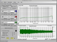
Reading a graph is easier than reading numbers. You don't need to even have numbers on the axis to get an idea where your frequency response is relative to any one point on the graph.
This plot uses the free software HolmImpulse. It is one of my speakers, but you can do the same thing with a line stage as if it was a loopback test.
Al you need is:
1. A computer
2. Sound card with a line input and line out
3. Some cables
4. HolmIpulse software
You do one sweep with the preamp bypassed and use that as a calibration run.
The sweep takes about a second or two to get meaningful information. You can then do the same with any other line stage to get a reference, but in either case the response should be ruler flat. If it is not, at least any changes you make you can see if you are making progress and you won't need a blindfold.
An externally hosted image should be here but it was not working when we last tested it.
I am still waiting to see quantitative measurements.
Fine Loren -easy enough to hook up.
I have a 'protoboard' here; give me a day or 2 - 3 (other commitments) and I will give you gain, frequency response, input impedance, output impedance. My distortion analyzer is on the blink right now but that does not seem to be in dispute. I have all the component values and there is a 12AU7 lying around here somewhere.
I will take the fed power amplifier input impedance as a low 22K. If anybody knows of a lower impedance commercial amplifier, kindly state. (My own notion is that they are mostly 100K.)
______________________________________________________________________________
PS: OK, Loren, just missed your post while typing/doing other things, and possibly misunderstood. You perhaps want quantative measurements specifically from Cassiel's amplifier, not in general to prove the case/circuit.
Last edited:
Do you know any tricks to improve bass response? Compared to a Bryston and a Mark Levinson's it lacks a little in that department.
Apparently the engineers cannot fix the bass in this thread
") But then again, where have they heard a ML?
But then again, where have they heard a ML?Several issues with your preamp.
First the 6SN7 simply cannot produce the bass that a good solid state circuit can. Not even if you connect 20 in parallel. Maybe it's due to microphonics. Who knows? In fact very few tubes are capable of near solid state - like bass. I only know the 6H30 but maybe there are others.
Second. You need a seriously overdone power supply - plenty microfarads in a CLC arrangements + solid state regulator.
Third. Despite my general dislike for the sound of cathode followers, a 6H30 follower does extremely impressive bass. With a CCS it may even become tolerable in the upper ranges.
And most importantly, all choices are about compromise. It is tremendously hard to preserve the midrange and fix the bass. If it were easy, all high end amplifiers would use exclusively tubes
Last edited:
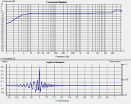
Well, since Loren insists....
I'm almost sure I did something wrong, maybe Loren can tell me.
Yes that doesn't look right at all
I think probably your levels are too low for starters (your impulse response should be a hell of a lot cleaner than that!! What did a loopback of the sound card look like?
Certainly if the FR curve presented is indicative of the FR of your preamp then I'm not surprised you think it sounds bass shy
rising response from about 500Hz up around 5db by 10Khz, and starts rolling off at around 80Hz down by 5 db by 20Hz.... edit: I can't find my loopback cable, but here is a quick and dirty measurement of my Sound Card preamp that I use for buffering stuff I'm testing. Not sure what is going on above 20K (I'm pretty sure it didn't used to do that) but it gives you an idea as to what you should be seeing. Note you should go into options and change to raw response rather than gated as well, when you are doing line level measurements
Tony.
Attachments
Several issues with your preamp.
First the 6SN7 simply cannot produce the bass that a good solid state circuit can. Not even if you connect 20 in parallel. Maybe it's due to microphonics. Who knows? In fact very few tubes are capable of near solid state - like bass. I only know the 6H30 but maybe there are others.
Second. You need a seriously overdone power supply - plenty microfarads in a CLC arrangements + solid state regulator.
Third. Despite my general dislike for the sound of cathode followers, a 6H30 follower does extremely impressive bass. With a CCS it may even become tolerable in the upper ranges.
And most importantly, all choices are about compromise. It is tremendously hard to preserve the midrange and fix the bass. If it were easy, all high end amplifiers would use exclusively tubes
Good to read this, it saves me a lot of time. So they can't compete with SS in the bass department, can they? It's OK, I still prefer tubes.
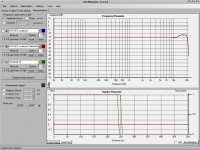
I think probably your levels are too low for starters
I think I have sorted out my amplitude problems. I'm still wary of false readings.
Attachments
Apparently the engineers cannot fix the bass in this thread
...First the 6SN7 simply cannot produce the bass that a good solid state circuit can. Not even if you connect 20 in parallel. Maybe it's due to microphonics. Who knows? In fact very few tubes are capable of near solid state - like bass. I only know the 6H30 but maybe there are others...
I am not sure where you get your information, but that is untrue for a line stage amp. The difference in frequency response between vacuum tubes and solid state will be indistinguishable.
I thought the engineers were still waiting for a genuine bass problem to be demonstrated. Demonstration has to precede diagnosis, which then must precede solution.analog_sa said:Apparently the engineers cannot fix the bass in this thread
Last edited:
I thought the engineers were still waiting for a genuine bass problem to be demonstrated. Demonstration has to precede diagnosis, which then must precede solution.
+1
- Status
- This old topic is closed. If you want to reopen this topic, contact a moderator using the "Report Post" button.
- Home
- Amplifiers
- Tubes / Valves
- Improving preamp's bass response.