Hi,
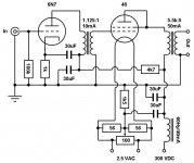
I'd like to know what interstage is adequate for a 45 tube instead of a 46. I found an interesting schematic at Vinylsavor blog
VinylSavor: 46
Also, I guess since it's not dual grid, The OPT is directly wired at the the anode.
Thanks
PG
I'd like to know what interstage is adequate for a 45 tube instead of a 46. I found an interesting schematic at Vinylsavor blog
VinylSavor: 46
Also, I guess since it's not dual grid, The OPT is directly wired at the the anode.
Thanks
PG
Attachments
Hi Pierre,
since the schematic shows an unloaded interstage transformer, it does not have an impedance of it's own. the impedance values given by transformer manufacturers are a guideline for the usage. You would want something like 20k for the 6N7. What is of concern is the primary inductance. You want a value well above 100Hy for the 6N7.
Best regards
Thomas
Puzzled
Thomas,
I'm a bit confused...
I wanted to give those values to Jack Galiano from Electra-Print and this was his answer:
If these Lundahls were 20K, the response on them at 13khz would be down 3-4db. 10ma 6n7’s may be lower than that.
You have to measure this number first. The 6SN7 is 10K
An impedance of 20K is too high for full bandwidth, too capacitive, really can’t be done by anybody realistically. Also, the inductance of 100H is not a workable number, if the trans sec is unloaded, then it would be near that, but if loaded correctly,
which it has to be to work full bandwidth, inductance would be around 20H. Transformers are not chokes. Operating them unloaded makes them a capacitor.
Did I miss something?
Hi!
Not always. In that amp I left the secondary of the interstage unloaded. Works beautifully. If you load it down to much, many advantages of interstage coupling get lost
Best regards
Thomas
I know terminations are necessary.
Not always. In that amp I left the secondary of the interstage unloaded. Works beautifully. If you load it down to much, many advantages of interstage coupling get lost
Best regards
Thomas
it does not have an impedance of it's own.
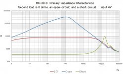
It's not true. Every transformer has a finite (frequency dependent) impedance.
For example this is a 8K/6R PP transformer. As you can see it does have a finite impedance when the secondary is open.
Attachments
Hi!
Yes, but what limits this impedance are the parasitics, primary inductance at the low frequency end and winding capacitances at the high frequency end. Of course there are other parasitics as well.
Every component has parasitics, capacitances and resistors for example have inductances.
Only when loaded on the secondary you get a useful impedance as with the red line in your graph.
Best regards
Thomas
What is the real load impedance then?
As a rule of thumb you can consider the impedance at 20-30 Hz which is given by the primary inductance as this is usually the lowest value in the audio band.
Manufacturers usually specify a range of source impedances for interstage transformers that will work. Higher source impedance will have more limitations at low frequency of course. However it could behave better at high frequency.
Hi!
You only get a 'real' load impedance, when you actually load the secondary.
Without loading the secondary the impedance is frequency dependant as shown in the example above. It will be very large at the mid frequencies.
Best regards
Thomas
What is the real load impedance then?
You only get a 'real' load impedance, when you actually load the secondary.
Without loading the secondary the impedance is frequency dependant as shown in the example above. It will be very large at the mid frequencies.
Best regards
Thomas
I would go for something like the Lundahl LL1660/10mA for the 6SN7 because has got 130H primary inductance and 80 Vrms headroom at 20Hz before saturation starts. Running the 6SN7 at 220V/10mA there would be enough headroom to drive the 45 even at 20Hz with acceptable distortion. At 220V/10mA I have found that NOS 6SN7GTB's have a typical gm of 3.3 mA/V. So I would expect -1dB around 15Hz using the above IT. It could well happen that one gets harmonic cancellation too....
Last edited:
I would go for something like the Lundahl LL1660/10mA for the 6SN7 because has got 130H primary inductance and 80 Vrms headroom at 20Hz before saturation starts.
Peter Treurniet's reply:
"Lundahls specifications for primary inductance are a bit unclear to me.
I have a LL1660S/PP here which is specified to have 290 H of primary inductance.
The transformer has 4 primary sections.
With my (professional) LCR meter I measure 7.7 H for each primary section.
Two sections in series give 23 H (a bitt less than the theoretical 7.7 x 4), and all sections in series give a bit less than 70 H.
Measured with Wayne Kerr 4210 digital LCR meter at 100 Hz. This is quite a bit less than the specification.
I am aware of the fact that inductance measurements depend very much on how the measurement is done, and normally give only a hint of how the situation is in practice (signal level; frequency).
For example look at inductance specifications of Plitron output transformers: huge primary inductances, but understandable because it is measured with 250 VAC / 50 Hz, instead of the typical 0.5 V at 100 Hz or so of a digital inductance meter.
Silicon steel shows higher inductance with higher signal at these low frequencies, and the Plitron specification is "impressive" until the way of measurement is taken into account.
I don't find the measurement protocol on Lundahls datasheet, but to me 290 H is too much off spec.
LL1660PP has a nongapped core; the 10mA and higher current types for SE applications will not meet their inductance specification because inductance will go down with an airgapped core"
I am afraid but you friend is a bit wrong. The proof is in the Pimms website measurement for the LL1635/5mA which gives more than 16K at 20 Hz when loaded with 20K. So the inductance can only be close to 130H...
There is little point in measuring the inductance at 100-120 Hz. To have a real figure for the headroom it should be measured at 50 Hz with small signal. To have a real figure for the effective load with large signal again it should be measured a 50 Hz because the lower the frequency the higher the distortion will be.
Lundahl inductances do match specified values at 50Hz with medium to large signal which is what matters at the end of the day....
Hi!
I agree with 45 on this. I know Pieter is an expert, but this doesn't match up with reality. I don't have a professional LCR meter but the LL1660 gives a good low frequency response with the 6N7 which has a high plate resistance. This wouldn't be possible if the inductance would be off by that much.
Instead of relaying such strong critisism through a friend on a public forum Pieter should discuss his findings with Per Lundahl directly and then report the outcome. Both are professionals in transformer winding and should be able to sort that mismatch out.
Best regards
Thomas
Pieter is not a friend of mine. I hardly know him. But I agree with him on the lack of measurement protocol by Lundahl. But would like to extend that to virtually all transformer builders. Perhaps they don't go around spewing specifications because so many other factors come into play when building something.
Then again I don't care about specs all that much. The proof of the pudding is in the eating for me.
Then again I don't care about specs all that much. The proof of the pudding is in the eating for me.
Last edited:
Hi!
I just wanted to express that I consider it bad style to relay such messages through another person, especially when it is critisism of a competitor. I know and like both Pieter and Per Lundahl and I respect them for their knowledge. I use the products of both of them in my designs.
I just pulled out my humble handheld LCR meter and measured the inductance of a LL1660/10mA. I get something like 25Hy for each primary which would be 100Hy when wired in series. I know that this meter is not very accurate for such measurements. In the past I did detailed inductance measurements using a signal gen and scope and running a frequency sweep across a resist and the inductance wired in series. Calculating the inductance from those measurements always gave higher values compared to that meter and typically closer to the spec of the transformer or choke under test.
As mentioned this also matches with the performance of these in actual amps. Would the inductance of the PP version really be only 23Hy, it would simply not work in many designs
Best regards
Thomas
Last edited:
- Status
- This old topic is closed. If you want to reopen this topic, contact a moderator using the "Report Post" button.
- Home
- Amplifiers
- Tubes / Valves
- 45 amp with 6N7