I recall you posting your supply specs but I didn't go digging through the thread to find them.
I'm sure you could find a thryratron that would work at that voltgage dorm pretty cheap. But it would take a bit of space. If I were you id look for some high voltage gto's and use them as the crow bar. There basically silicon control rectifiers. You don't need a hockey puck though. The trigger circuit could be a basic current sensing resistor or the right size the switches on a transistor. That intern sends clamping voltage to the scr. They don't usually take more then a few volts. You could probably use a 9 volt to make hv isolation easier.
Just to let you know what I meant by hockey puck. Big high voltage and current gto' are the same size and shape as a hockey puck. Hence there nick name.
I'm sure there are other semiconductor options. Just not thinking of them at the moment. But scr's are the #1 device for this low voltage.
But just to let you know, the resistor online can be just as effective in protecting things from a filter discharge.
Nick
Sent from my Garminfone using Tapatalk
I recall you posting your supply specs but I didn't go digging through the thread to find them.
I'm sure you could find a thryratron that would work at that voltgage dorm pretty cheap. But it would take a bit of space. If I were you id look for some high voltage gto's and use them as the crow bar. There basically silicon control rectifiers. You don't need a hockey puck though. The trigger circuit could be a basic current sensing resistor or the right size the switches on a transistor. That intern sends clamping voltage to the scr. They don't usually take more then a few volts. You could probably use a 9 volt to make hv isolation easier.
Just to let you know what I meant by hockey puck. Big high voltage and current gto' are the same size and shape as a hockey puck. Hence there nick name.
I'm sure there are other semiconductor options. Just not thinking of them at the moment. But scr's are the #1 device for this low voltage.
But just to let you know, the resistor online can be just as effective in protecting things from a filter discharge.
Nick
Sent from my Garminfone using Tapatalk
Hi ,
I would use one or two photo transistors as arc sensor in combination with an overcurrent detector. A lock relay establish a safety circuit. In event of a shorted capacitor or an arc over, the relay becomes dead and drop out. Another option is a primary circuit breaker with an voltage release coil. Both of these measures are common practise in commercial equipment.
In my homebrew 400W amp I use the latter. A combined circuit consist of an overvoltage detector for Vg2, a Vg1 undervoltage detector , and a plate overcurrent detector trigger the main circiut breaker and a SCR. This device dicharge the main capacitors via a dumping resistor.
Ok, the SCR solution is not an option for 2500V, but my amp runs only with 500V.
73
Wolfgang
You wrong. Relays are never used in crowbars. You don't know what your talking about. And I said use a gto which is a type of scr. They go up to 6000 volts.
Do some homework before ya speak Wolfgang.
And learn about crowbars before you try and give some advice.
the reason relay are not used is there switch time. From the time a relays coil is energised to when it switches is in the milliseconds. More then enough time for a discharge event to happen completely. A gto's turn on time is in the microseconds.
And how would you use a photo transistor to detect arcs on a bright filament tube?
I've used them in waveguide. But they are void of light. Photo diodes or transistors would be useless.
Nick
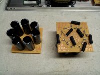
I completed the C1 capacitor banks, with (7) 150uF, 450V TSHA caps and (7) 47K 5W resistors in each. Everything measures fine at 21uF and 329K for each bank. The caps are spaced apart for air circulation and cooling and I may also put some hot melt glue between them for further mechanical strength. The resistors are lifted about 1/8" off the board for the same reason. I can bend them further off the board when I install in the amps if space permits.
As with the rectifier stack, I removed all the solder pads near the HV connections and coated the connections and the board with high dielectric acrylic conformal coating (1500V/mil thickness) to help prevent arcing or surface discharges. I prefer the acrylic to urethane or silicone varieties of conformal coating because it is quick drying, easily removed with solvent and can even be soldered through without removing if you're in a hurry. I think coatings are an often neglected area in DIY - they can offer a lot of benefits for not much cost or effort.
As with the rectifier stack, I removed all the solder pads near the HV connections and coated the connections and the board with high dielectric acrylic conformal coating (1500V/mil thickness) to help prevent arcing or surface discharges. I prefer the acrylic to urethane or silicone varieties of conformal coating because it is quick drying, easily removed with solvent and can even be soldered through without removing if you're in a hurry. I think coatings are an often neglected area in DIY - they can offer a lot of benefits for not much cost or effort.
Attachments
Last edited:
I completed the C1 capacitor banks, with (7) 150uF, 450V TSHA caps and (7) 47K 5W resistors in each. Everything measures fine at 21uF and 329K for each bank. The caps are spaced apart for air circulation and cooling, and the resistors are lifted about 1/8" off the board for the same reason. I can bend them further off the board when I install in the amps if space permits. I may also put some hot melt glue between them for further mechanical strength.
As with the rectifier stack, I removed all the solder pads near the HV connections and coated the connections and the board with high dielectric acrylic conformal coating (1500V/mil thickness) to help prevent arcing or surface discharges. I prefer the acrylic to urethane or silicone varieties of conformal coating because it is quick drying, easily removed with solvent and can even be soldered through without removing if you're in a hurry. I think coatings are an often neglected area in DIY - they can offer a lot of benefits for not much cost or effort.
1/8 is a little close. I would almost have them perpendicular to the board. I would not use hot glue on anything in the high voltage circuit. In high voltage heat is a double whammy. It causes air to ionizing and flash over. The more space between components the better.
1/8 is a little close. I would almost have them perpendicular to the board. I would not use hot glue on anything in the high voltage circuit. In high voltage heat is a double whammy. It causes air to ionizing and flash over. The more space between components the better.
Like I said, when I get ready to install them in the amps I'll know better how much room I have and how best to orient them. I do envision bending them further away from the board, but it doesn't make sense to do that before I know the ultimate layout.
The amps will have forced air cooling with a fan mounted under the 833 sucking pre-heated air from the chassis and directing it up around the 833. I'll orient the air intake slots to ensure that cool air is directed over the resistors and rectifier diodes.
Oh, and the hot melt glue would go between the bases of the caps on top of the board, not on the resistors - I re-read the post above and realized it might be misinterpreted that way so I edited it...
Last edited:
Like I said, when I get ready to install them in the amps I'll know better how much room I have and how best to orient them. I do envision bending them further away from the board, but it doesn't make sense to do that before I know the ultimate layout.
The amps will have forced air cooling with a fan mounted under the 833 sucking pre-heated air from the chassis and directing it up around the 833. I'll orient the air intake slots to ensure that cool air is directed over the resistors and rectifier diodes.
Oh, and the hot melt glue would go between the bases of the caps on top of the board, not on the resistors - I re-read the post above and realized it might be misinterpreted that way so I edited it...
Ok I see. Ya those big caps could use more support. Are you going to have a filter on the fans? The only reason I ask is high voltage attracts dust. And dust can make a good discharge path.
I've got more experience with big high voltage equipment then any other area of electronics. Just trying to pass on anything that I think might help you is all.
Nick
Thanks, I appreciate your input. I'll have some type of low resistance filters on the air intake slots, to minimize the amount of dust that gets in. That's another reason I'm applying the conformal coating as well - dust can't form a discharge path if the circuit is coated with a barrier.
That's good. The more dust you keep out. The less headaches you get, lol.
As for coating, you can us some corona dope.its made by gc electronics. Its a thicker then regular paint. Has a little brush in the bottle with it. Kind of like fingernail polish. Its made exactly for this purpose.
Just don't put a lime in it and drink it what ever you do. Not that kind of corona,lol.
Ya I know, corny. Just can't help myself sometimes.
here's a link to a place that sells it.
GC Electronics 10-4702: Corona Dope, 2-oz. Bottle
There is also red varnish that work pretty good for this application but the corona dope is by far the best.
Nick
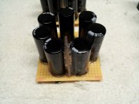
I went ahead and hot glued the bases of the caps in the C1 bank for added mechanical strength, and I glued a strip of Lexan polycarbonate between the first and last caps in the bank for added electrical insulation, since the metal cans of those caps have 2000V potential difference between them. See Pic.
Now onto the big C2 bank!
Now onto the big C2 bank!
Attachments
That Corona Dope looks like good stuff; similar to the MG Chemicals conformal coating I'm using but with a higher dielectric strength. Maybe I'll pick up a bottle, but I won't put it on the stuff I've already coated...never know if it's compatible or not.
Thanks for the tip.
Thanks for the tip.
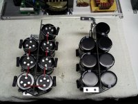
I completed the two mirror-imaged C2 cap banks (see pics). They test at 127uF and 126uF at 120Hz using my LCR meter, a little lower than nominal but well within the 20% spec. The balancing resistors will be bent away from the caps when the banks are mounted; for now they take up less space flat against the caps.
The banks are constructed on a Lexan panel with the caps in series order around the panel. The panel serves to separate the caps with the highest potential difference from each other, and also gives rigidity and a place to mount the brackets. The banks will be screwed to the side panels of the enclosure underneath the OPT; I left some clearance at the back of the panel so the cap vents can expel their contents if something goes wrong. Caps are secured with hot-melt glue and zip-ties through holes in the panel.
The banks are constructed on a Lexan panel with the caps in series order around the panel. The panel serves to separate the caps with the highest potential difference from each other, and also gives rigidity and a place to mount the brackets. The banks will be screwed to the side panels of the enclosure underneath the OPT; I left some clearance at the back of the panel so the cap vents can expel their contents if something goes wrong. Caps are secured with hot-melt glue and zip-ties through holes in the panel.
Attachments
My own Midlife Crisis 833C Amp
Hi,
This is an very intresting thread, because I was starting my own "Midlife Crisis 833C Amp" nearly at the same time (On March 18 I was ordering two of this "Monster-Tubes" to playing around with this ).
).
So I try to discribe this project in my bad english...
The starting Point was the german "silvercore-project". But in my opinion is 15W out of this Monsters like sex with no touching. For this I don't need to build a new amp, I could use some of my older projects...
The frist step were a lot of simulations with LTSpice...and some tests with the B+
The Picture shows the current and at the voltage near 1kV...
833c Test | 833ctest | hifi-forum.de Bildergalerie
And yes, the Spice-model of the 833A is far away from real 833C!
I was calculating the amp for about 50W sine...makes a B+ of about 1kV and a bias current of 200mA.
The reason were, I want to use normal available parts for all... And 1kV is much more handy like 2.3kV...Over all it was expensive enough to be an "Midlife Crisis Amp" also.
The first two stages are build from one 12AT7 followed by an SRPP (2 x 6CV7/EL34) in triode mode driving the 833 with up to 100V peak to peak
trough an electolytic capacitor of 47uF (briged by 100nF MKP).
I use a lot of Hammond transformers, including the OTP 1642SE.
Kupfer und Eisen...1642SE | eisen1642se, kupfer | hifi-forum.de Bildergalerie
Ok, the 8ohm outputs of this transformers are useless, but because I have 8ohm speakers only I can use the 16ohm output so I have a Raa of 10kohm and this seems to fit perfectly for the 833C...
Here some photos of one the ready monoblocks...while testing...
833C Endtest | 833c, endtest | hifi-forum.de Bildergalerie
SAM 0226 | sam0226 | hifi-forum.de Bildergalerie
833c | 833c | hifi-forum.de Bildergalerie
And some scope photos...
833C 20Hz | 20hz, 833c | hifi-forum.de Bildergalerie
833C 100Hz | 100hz, 833c | hifi-forum.de Bildergalerie
833c 1KHz | 1khz, 833c | hifi-forum.de Bildergalerie
833C 10 kHz | 10, 833c, khz | hifi-forum.de Bildergalerie
SAM 0234 | sam0234 | hifi-forum.de Bildergalerie
power...About 60V peak to peak are 50W sine...
833C 50W Audio | 50w, 833c, audio | hifi-forum.de Bildergalerie
And some photos at live action...
833C Amp | 833c | hifi-forum.de Bildergalerie
833C | 833c | hifi-forum.de Bildergalerie
833C Amp | 833c | hifi-forum.de Bildergalerie
Matthias.
Hi,
This is an very intresting thread, because I was starting my own "Midlife Crisis 833C Amp" nearly at the same time (On March 18 I was ordering two of this "Monster-Tubes" to playing around with this
).So I try to discribe this project in my bad english...
The starting Point was the german "silvercore-project". But in my opinion is 15W out of this Monsters like sex with no touching
. For this I don't need to build a new amp, I could use some of my older projects...The frist step were a lot of simulations with LTSpice...and some tests with the B+
The Picture shows the current and at the voltage near 1kV...
833c Test | 833ctest | hifi-forum.de Bildergalerie
And yes, the Spice-model of the 833A is far away from real 833C!
I was calculating the amp for about 50W sine...makes a B+ of about 1kV and a bias current of 200mA.
The reason were, I want to use normal available parts for all... And 1kV is much more handy like 2.3kV
...Over all it was expensive enough to be an "Midlife Crisis Amp" also.The first two stages are build from one 12AT7 followed by an SRPP (2 x 6CV7/EL34) in triode mode driving the 833 with up to 100V peak to peak
trough an electolytic capacitor of 47uF (briged by 100nF MKP).
I use a lot of Hammond transformers, including the OTP 1642SE.
Kupfer und Eisen...1642SE | eisen1642se, kupfer | hifi-forum.de Bildergalerie
Ok, the 8ohm outputs of this transformers are useless, but because I have 8ohm speakers only I can use the 16ohm output so I have a Raa of 10kohm and this seems to fit perfectly for the 833C...
Here some photos of one the ready monoblocks...while testing...
833C Endtest | 833c, endtest | hifi-forum.de Bildergalerie
SAM 0226 | sam0226 | hifi-forum.de Bildergalerie
833c | 833c | hifi-forum.de Bildergalerie
And some scope photos...
833C 20Hz | 20hz, 833c | hifi-forum.de Bildergalerie
833C 100Hz | 100hz, 833c | hifi-forum.de Bildergalerie
833c 1KHz | 1khz, 833c | hifi-forum.de Bildergalerie
833C 10 kHz | 10, 833c, khz | hifi-forum.de Bildergalerie
SAM 0234 | sam0234 | hifi-forum.de Bildergalerie
power...About 60V peak to peak are 50W sine...
833C 50W Audio | 50w, 833c, audio | hifi-forum.de Bildergalerie
And some photos at live action...
833C Amp | 833c | hifi-forum.de Bildergalerie
833C | 833c | hifi-forum.de Bildergalerie
833C Amp | 833c | hifi-forum.de Bildergalerie
Matthias.
Hi Magz,
The Sound is gigantic, like the tubes...
It sounds better than the best 300B I have, but with much more power!
This is a tube amp that sounds like a tube amp but with the power of a transistor amp. When I use the Klipsch Cornwalls it is like an earthquake at higher volume and with very small compact speakers it works also...so you don't miss a subwoofer.

As you can see at this pic there are about 60V peak to peak at a 8ohm load...50W sine without anny clipping (The blue curve, the yellow is the Input Signal). The amp clips at about 60W. ( By the way, the Driver stage is clipping first)
Matthias
The Sound is gigantic
, like the tubes...It sounds better than the best 300B I have, but with much more power!
This is a tube amp that sounds like a tube amp but with the power of a transistor amp. When I use the Klipsch Cornwalls it is like an earthquake at higher volume
and with very small compact speakers it works also...so you don't miss a subwoofer.
As you can see at this pic there are about 60V peak to peak at a 8ohm load...50W sine without anny clipping (The blue curve, the yellow is the Input Signal). The amp clips at about 60W. ( By the way, the Driver stage is clipping first
) Matthias
I'm on the road this week and replied yesterday but apparently it didn't post.
I'm still waiting for my OPTs and HV chokes so I'm taking my time and building subunit by subunit and testing each. Next are the DC supplies for 6E5P heater and 833 cooling fan, then the driver circuit. Then I'll determine the best location for each to give the least noise and shortest signal path, then drill the holes, then get the panels anodized/powder coated/mirror polished, then finally assembled.
I'll be sure to bring it all up on a variac, and the bias supplies are regulated so I can adjust them as needed to get the target Ia.
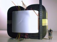
I received an update from Monolith on the progress of my OPTs. The amorphous cores have been received and the bobbins have been wound. Performance is a little better than specification:
L=68H (spec>60 H)
-3dB FR = 7Hz - 66kHz (spec 8Hz - >60kHz)
32 Hz saturation frequency at 1400 Vrms input (spec <35 Hz)
Attached is a picture of the core from one OPT with the bobbin in place. Note the teflon dielectric. An metric ruler and an ECC83 are in the picture for size reference.
They are still waiting on the laser-cut enclosures; once those arrive the OPTs will be assembled and on the way to me!
Attachments
- Home
- Amplifiers
- Tubes / Valves
- The Midlife Crisis - My 833C Amp Build