Maybe you can get away without, but balancing resistors can help reliability - and suitable parts can be procured to make it easy.
For example, I use the Welwyn MH37 series, which are rated for 3500V, and are almost as cheap as ordinary resistors:
MH37-470KJI - WELWYN - RESISTOR, H/V 0.5W 470K | Farnell United Kingdom
One more subtle reason for using them: Before the diodes break down destructively, you can sometimes get transient breakdown/leakage effects, that may not destroy the diode, but cause a lot of noise.
Especially if you choose to avoid balancing resistors, I would recommend a fuse in the PT secondary winding circuit - rated to be able to manage the HT voltage. A microwave cooker fuse is made for 5kV, and may be useful, depending on the VA rating of the PT:
Microwave Oven High Voltage Fuse 800mA 0.8A 5kV | eBay
A fuse in the secondary gives closer control, since the power-ON surge needs no accounting for.
Hi ,
if you employ separate transformers for HV and the rest of all required voltages, you can secure the circuit with a fuse on the primary side.
To protect the HV windings from arc over due transients , attach a small value capacitor across. Any capacitor betweeen 1 to 5 nF / 5kV will be suitable.
And why a bridge rectifier from single diodes? This one here delete all discussions about reverse voltage balancing.
HV bridges are availble here:
http://ixdev.ixys.com/DataSheet/uge.pdf
And if you like to fiddle with diodes , 4 pcs microwave oven diodes can complete a bridge without any further measures.

73
Wolfgang
Maybe you can get away without, but balancing resistors can help reliability - and suitable parts can be procured to make it easy.
For example, I use the Welwyn MH37 series, which are rated for 3500V, and are almost as cheap as ordinary resistors:
MH37-470KJI - WELWYN - RESISTOR, H/V 0.5W 470K | Farnell United Kingdom
One more subtle reason for using them: Before the diodes break down destructively, you can sometimes get transient breakdown/leakage effects, that may not destroy the diode, but cause a lot of noise.
Especially if you choose to avoid balancing resistors, I would recommend a fuse in the PT secondary winding circuit - rated to be able to manage the HT voltage. A microwave cooker fuse is made for 5kV, and may be useful, depending on the VA rating of the PT:
Microwave Oven High Voltage Fuse 800mA 0.8A 5kV | eBay
A fuse in the secondary gives closer control, since the power-ON surge needs no accounting for.
Its common practice to put a high wattage wire wound resistor in series with the plate line. Something around 50 ohms works well. It doesnt create much of a voltage drop during normal operation. But if something were to arc over it would quench the arc since an arc draw massive amounts of current. The main thing to remember is you do not want the arc to sustain its self long enough to discharge the filter capacitors. That is were the real damage happens.
A fuse does help. And the one mentioned would be great. but high voltage fuses can sometimes be a bit difficult to source. At least in low current levels.
Then theres the option of using a small metal film resistor as a fuse. I seen the menstioned many times but I have never done this.
Since tour amp will be running at such a high voltage, you will need some metthod of protecting you investment in those output transformers. Id suggest a fuse and a resistor in series with the plate.
The resistor acts as your primary safeguard and the fuse as a backup. And or course theres the circuit breaker on the primary. But thats not really usinful in protecting things. Mainly just preventing fires.
Nick
Thanks Rod and Funker and Nick,
I have been thinking about fusing the HV separately - it is from a dedicated transformer, so that should be a simple matter. It also will have a soft start circuit capable of 20A on the primary, so that should help with turn-on transients. I'll consider the small series resistor, Nick.
Funker, I guess I didn't just buy a pre-made HV bridge for a couple reasons. One, I kind of like the challenge of making my own. Two, I would like to avoid the reverse recovery spike from a standard rectifier; I use Schottky diodes whenever I can. I even thought about using Xenon rectifiers in a bridge but the added filament xrmr, weight, and four hazardous HV top caps per unit pushed me to SS. These monos will be HUGE and HEAVY enough as is...
Last edited:
To all who have expressed concern - thank you and relax, please. I'm doing a few experiments to generate some data to help answer the question about the need for balancing resistors. Let's see what the data tell us; frankly, this is the part of this hobby that I like the most. I guess it's hard to take 30+ years as a research scientist out of my blood, and I've always been much more of an experimentalist than a theorist.
I have no intention of killing myself or anyone else with this project. It's called the Midlife Crisis, not the Death Wish.
I have no intention of killing myself or anyone else with this project. It's called the Midlife Crisis, not the Death Wish.
350V will kill one as readily as 900V. So, precautions apply to all of us doing tubes. I'm sure that you have a healthy respect and fear for the high voltage, or else you wouldn't do this.
120 volt ac IS the most dangerous. Higher is actually a bit safer. To a point though. If your a linemen for the power company it doesnt matter what your working on, LOL.
I didnt think youd hurt yourself. Just passing on different option to you to use on your final build.
Nick
discussion is about semi-diodes, but how about gas rectifiers... can withstand up to 10k
i know they are PITA because of filament requirements, but one can do with thick wire few turns on big toroid 230/12...
and you get 12v "for free", for your pwr managment circuits
I mentioned in Post#143 that I did consider Xenon gas rectifiers, but I had to make some choices to try to keep these things in one chassis per mono, and going to SS rectification was one of the choices.
Experimental results:
I had previously checked the DC voltage across each diode in all four legs of each high voltage diode bridge with 166VDC output from the bridge, and the % difference between the high and low diodes in each leg ranged from 0.6% up to 4.5%.
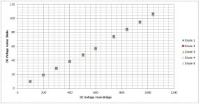
That told me about low voltage behavior, but there was no guarantee that behavior would be the same at high voltage, so I hooked up my Hammond 733A transformer to a variac, connected it to one of the bridges and ran up the DC voltage out of the bridge from 100V to 1040V, in ~100V increments, measuring the DC across all the diodes in one leg of the bridge at each point. The results appear in the graph below.
As you can see, the five diodes appear to share voltage superbly all the way up to 1000V+ bridge voltage, or 40% of the way to the target 2500V. The relationship is very linear, with R-squared = 0.998. At 100VDC bridge voltage, the difference between high and low diode is .16V, and at 1040V it is 1.6V. It's almost like I made the numbers up! But I didn't.
Now, the only caveat I can think of is that this was a naked bridge with no filter and only a multimeter for a load, so the total current was only on the order of a milliamp or so, but the voltage sharing behavior appears to be near perfect. Higher forward currents would cause the temperature to rise a bit, which could affect the results, but I can't see it getting to the point where there would be a problem, especially with (5) 1200V diodes in each leg.
Am I missing something here?
PS: The wider gap in voltage after 600V is where I shut down for a moment and switched to a 5000V multimeter probe, in case you are interested.
.
I had previously checked the DC voltage across each diode in all four legs of each high voltage diode bridge with 166VDC output from the bridge, and the % difference between the high and low diodes in each leg ranged from 0.6% up to 4.5%.
That told me about low voltage behavior, but there was no guarantee that behavior would be the same at high voltage, so I hooked up my Hammond 733A transformer to a variac, connected it to one of the bridges and ran up the DC voltage out of the bridge from 100V to 1040V, in ~100V increments, measuring the DC across all the diodes in one leg of the bridge at each point. The results appear in the graph below.
As you can see, the five diodes appear to share voltage superbly all the way up to 1000V+ bridge voltage, or 40% of the way to the target 2500V. The relationship is very linear, with R-squared = 0.998. At 100VDC bridge voltage, the difference between high and low diode is .16V, and at 1040V it is 1.6V. It's almost like I made the numbers up! But I didn't.
Now, the only caveat I can think of is that this was a naked bridge with no filter and only a multimeter for a load, so the total current was only on the order of a milliamp or so, but the voltage sharing behavior appears to be near perfect. Higher forward currents would cause the temperature to rise a bit, which could affect the results, but I can't see it getting to the point where there would be a problem, especially with (5) 1200V diodes in each leg.
Am I missing something here?
PS: The wider gap in voltage after 600V is where I shut down for a moment and switched to a 5000V multimeter probe, in case you are interested.
.
Attachments
Last edited:
Experimental results:
I had previously checked the DC voltage across each diode in all four legs of each high voltage diode bridge with 166VDC output from the bridge, and the % difference between the high and low diodes in each leg ranged from 0.6% up to 4.5%.
That told me about low voltage behavior, but there was no guarantee that behavior would be the same at high voltage, so I hooked up my Hammond 733A transformer to a variac, connected it to one of the bridges and ran up the DC voltage out of the bridge from 100V to 1040V, in ~100V increments, measuring the DC across all the diodes in one leg of the bridge at each point. The results appear in the graph below.
As you can see, the five diodes appear to share voltage superbly all the way up to 1000V+ bridge voltage, or 40% of the way to the target 2500V. The relationship is very linear, with R-squared = 0.998. At 100VDC bridge voltage, the difference between high and low diode is .16V, and at 1040V it is 1.6V. It's almost like I made the numbers up! But I didn't.
Now, the only caveat I can think of is that this was a naked bridge with no filter and only a multimeter for a load, so the total current was only on the order of a milliamp or so, but the voltage sharing behavior appears to be near perfect. Higher forward currents would cause the temperature to rise a bit, which could affect the results, but I can't see it getting to the point where there would be a problem, especially with (5) 1200V diodes in each leg.
Am I missing something here?
PS: The wider gap in voltage after 600V is where I shut down for a moment and switched to a 5000V multimeter probe, in case you are interested.
.
Hi ,
here some useful informations about rectifier diodes.
Frequently Asked Questions about VMI's High Voltage Diodes"
73
Wolfgang
I would still use resistors to ensure voltage balance. Why play games with this stuff? Just use the resistors and be done with it. The peace of mind will be well worth the extra few bucks you spend. I can't speak for anyone else on here, but every time I've cheaped out on something it has came back to bite me.
Hi ,
here some useful informations about rectifier diodes.
Frequently Asked Questions about VMI's High Voltage Diodes"
73
Wolfgang
Interesting. From that reference:
Question: When diodes are used in a bridge or string configuration is it necessary to place equalizing resistors across the diodes? Also, is it necessary to place capacitors in parallel with the equalizing resistors to reduce noise and high voltage spikes?
Answer: Balancing resistors and capacitors are generally not required when using VMI diodes. A resistors connected in parallel with a rectifier is intended to balance the reverse bias voltage across the series rectifiers. As such, the resistor value needs to be selected such that the current through the resistor is fairly large compared to the reverse leakage of the diode, thereby making a stiff divider circuit. If there are relatively high leakage currents expected in the diode, this can result in a significant power loss in the balancing resistors.
Capacitors connected in parallel to resistors/diodes can be used to balance voltages across diodes during transient conditions, or ringing. Care must be taken to select the capacitors small enough so as not to impact the rectified waveform at the output of the diode.
VMI's diodes are well-balanced for Ir and reverse recovery time (Trr).
Many of VMI's diodes have up to twenty junctions in series. The series junctions operate under many kinds of applications, and all sorts of conditions without compensating resistors or capacitors with no problems.
My diodes aren't VMI diodes, but that does agree with my experimental results for the Cree SiC Schootky diodes.
I would still use resistors to ensure voltage balance. Why play games with this stuff? Just use the resistors and be done with it. The peace of mind will be well worth the extra few bucks you spend. I can't speak for anyone else on here, but every time I've cheaped out on something it has came back to bite me.
I understand your sentiment. It's not about being cheap - hell I'm spending $10K on parts here! It's about adding an additional level of complexity and additional failure modes to the rectifier bridge. My concern is that a "belt and suspenders" approach of adding resistors because they "can't hurt" may actually decrease the reliability.
Looking at the 1000V data, I get 1.6% difference between the highest and lowest diode, or let's even round up to 2%. If at full power I end up with a total of 500V across each diode that's a maximum difference of 10V in the stack, while each diode has 700V of headroom. If operating at higher currents and temps changes the relationship between the highest and lowest diode by a factor of 10X I still have an extra 600V headroom to spare.
Interesting. From that reference:
Question: When diodes are used in a bridge or string configuration is it necessary to place equalizing resistors across the diodes? Also, is it necessary to place capacitors in parallel with the equalizing resistors to reduce noise and high voltage spikes?
Answer: Balancing resistors and capacitors are generally not required when using VMI diodes. A resistors connected in parallel with a rectifier is intended to balance the reverse bias voltage across the series rectifiers. As such, the resistor value needs to be selected such that the current through the resistor is fairly large compared to the reverse leakage of the diode, thereby making a stiff divider circuit. If there are relatively high leakage currents expected in the diode, this can result in a significant power loss in the balancing resistors.
Capacitors connected in parallel to resistors/diodes can be used to balance voltages across diodes during transient conditions, or ringing. Care must be taken to select the capacitors small enough so as not to impact the rectified waveform at the output of the diode.
VMI's diodes are well-balanced for Ir and reverse recovery time (Trr).
Many of VMI's diodes have up to twenty junctions in series. The series junctions operate under many kinds of applications, and all sorts of conditions without compensating resistors or capacitors with no problems.
My diodes aren't VMI diodes, but that does agree with my experimental results for the Cree SiC Schootky diodes.
Hi ,
it is always advisible to make themself a mind about things before starting to work on a project. This will safe time & money.
I understand your approach. But the don´t overegg the pudding.
ordinary rectifier diodes like a common 1N4007 withstand a reverse voltage of 1000V , the forward loss is appr. 0,7V at 1A.
Several years ago I build an Power supply for an rf amp (ham use) .
The plate voltage was also 2500V d.c. I made a h.v. bridge with 1N4007 , each leg employed 7 e.a. of the latter. So 7 diodes share 2500V reverse volts . I had no resistors and no capacitors, just the 28 diodes.
The power unit run from the first time without any troube so far.
In an audio amp , snubber capacitors across each diode make sense to subdue noise etc, if you use ordinary diodes. With your schottky´s are such capacitors not neccessary.
good luck with yor amazing project.
73
Wolfgang
The caps on this thing could cause ball lightning.
Uh no. Ball lightning is shrouded in myth but I don't think he's running that kinda b+.
The caps on this thing could cause ball lightning.
Only 378 Joules of storage per mono...
Are you going choke input or will that be a pi network?
with that kind of capacitance at that voltage you definitely want a low resistance high wattage resistor between the supply and the output transformer. If it arced over under chassis or worse in the output it would destroy pretty much all of it.
Lol, maybe you should look into a crow bar for it. To protect your investment. It would probably be a good idea. What's your b+ again?
Nick
Are you going choke input or will that be a pi network?
with that kind of capacitance at that voltage you definitely want a low resistance high wattage resistor between the supply and the output transformer. If it arced over under chassis or worse in the output it would destroy pretty much all of it.
Lol, maybe you should look into a crow bar for it. To protect your investment. It would probably be a good idea. What's your b+ again?
Nick
LCLC Choke input on all circuits (I posted the PSUD charts a few pages back). 35H choke on the 2300V 833C B+, 13H choke on the 450V 6E5P B+, 2.5mH choke on the 10V, 10A 833C filament supply. Soft start circuit on the 833C B+ transformer primary.
I've been looking into a crowbar circuit for OPT protection. Those Monoliths deserve some protection.
- Home
- Amplifiers
- Tubes / Valves
- The Midlife Crisis - My 833C Amp Build