Hi,
@ Unison845
No, i did'nt do any plot...(I'm plottintg with my ears") )
)
The 1642SE is a good OPT but you should'nd use the 8Ohm tap.
There is a lot of drop over 8kHz... the 4Ohm and the 16 Ohm taps are OK.
As you can see in my pictures it is very linear at the 16Ohm tap. Normaly the 1642SE has a Raa of 5kOhms, so if you use it with 8Ohm speakers at the 16Ohm tap, it works very well - with a Raa of 10kOhms seen at the 833...
Hope that my HP-Audio Analyzer will be delivered at this week, so I can do a lot of more measurements...
Greetz, Matthias.
@ Unison845
No, i did'nt do any plot...(I'm plottintg with my ears
)The 1642SE is a good OPT but you should'nd use the 8Ohm tap.
There is a lot of drop over 8kHz... the 4Ohm and the 16 Ohm taps are OK.
As you can see in my pictures it is very linear at the 16Ohm tap. Normaly the 1642SE has a Raa of 5kOhms, so if you use it with 8Ohm speakers at the 16Ohm tap, it works very well - with a Raa of 10kOhms seen at the 833...
Hope that my HP-Audio Analyzer will be delivered at this week, so I can do a lot of more measurements...
Greetz, Matthias.
@Magz
You are right... there is a lot of "Vooodooo" around Cords and cables...But I think a wire is a wire...no more...
But I thinkk also, every weight on copper and iron you use in the OPT is better than mgrams of Gold you are use in power Cords...
Matthias.
PS: because I'm a newbe here, it needs a lot of time, my Posts are shown....please admin, I 'm a newbee, but my Posts are all ok... so please, let me post! In nearly realtimeme...
Well, you know what they say...the heart of an SET is the output transformer. Why skimp there?
Hell, there are people in this hobby who spend that much on a powercord! I consider this a much more sensible investment.
You are right... there is a lot of "Vooodooo" around Cords and cables...But I think a wire is a wire...no more...
But I thinkk also, every weight on copper and iron you use in the OPT is better than mgrams of Gold you are use in power Cords...
Matthias.
PS: because I'm a newbe here, it needs a lot of time, my Posts are shown....please admin, I 'm a newbee, but my Posts are all ok... so please, let me post! In nearly realtimeme...
Hello Matthias,
Thanks for the response.
I built a pair on 833 amp about 10 years ago, I dont listen to them anymore since I have few other amp to play with, but I am interested in upgrading them with better output transformer.
A few years ago a friend bought a pair of 1642 SE (about $600/pr), they are OK but not great, since it has peaking at 20Khz, and low frequency distortion when loaded over 150ma.
You sine wave waveform looked surprisingly good, that's why I am interested to see the frequency response across the spectrum for your amp to see if there is any issue with the output transformer.
Did you buy the HP 8903 audio analyzer? I have one myself and it is a great instrument.
Please post your amp frequency response when you have a chance to measure it.
Thank you.
Hi,
@ Unison845
No, i did'nt do any plot...(I'm plottintg with my ears
The 1642SE is a good OPT but you should'nd use the 8Ohm tap.
There is a lot of drop over 8kHz... the 4Ohm and the 16 Ohm taps are OK.
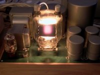
As you can see in my pictures it is very linear at the 16Ohm tap. Normaly the 1642SE has a Raa of 5kOhms, so if you use it with 8Ohm speakers at the 16Ohm tap, it works very well - with a Raa of 10kOhms seen at the 833...
Hope that my HP-Audio Analyzer will be delivered at this week, so I can do a lot of more measurements...
Greetz, Matthias.
Attachments
Thank you for letting me know re Monolith Magnetics. I have already been in touch with this company and they have quoted me $ 2,200 for a pair of Output Transformers. I am confident they will be well worth it and will be ordering then soon. In the meantime I will watch with interest how you get on with yours and would appreciate your opinion on them.
Monolith Magnetics, located in Belgium. BTW, I don't have them yet, that's an in-construction photo from them.
MONOLITH MAGNETICS
.
Good morning Matthias..
Glad to read that your 833A amplifier is up and running...that 833A makes a nice room heater.
Some of the older 1 kw tube AM broadcast transmitters use four 833A's, two in parallel in the RF final amplifier, and two in push-pull for the modulator. The Gates Radio units used a pair of 807's to drive the P-P 833A modulator. The HT supply delivers approximately 2500 volts, the HT plate transformer delivers approximately 3000 volts at 1 ampere each side of center, and the rectifiers were mercury vapor 8008's or 575A's. You can see the flashing in the rectifiers in sync with audio modulation. To get 1 kw RF out of the transmitter, the final RF amplifier ran 2500 volts and 560 mA on the plates...and the two 833A's in the modulator delivered approximately 650 watts (in class B) to modulate the RF. The distortion measured fairly low with good tubes.
The glowing plate is normal with the 833A...just make sure the tube gets plenty of air and isn't boxed in by components. Use the heat radiating connector for the plate in particular. There is a maximum seal temperature spec for the 833A (as with most other power tubes). Treat the 833A right, and you will get long life and good service from it.
I haven't built a SE amplifier in a long time....my concern has been unbalanced DC in the output transformer primary, core saturation and resulting distortion. Since the single ended RF final is the "load" for the modulator in a broadcast transmitter, the DC current for the RF final runs through a high inductance choke, and the audio from the modulation transformer is coupled through a large value high voltage capacitor (to keep the DC out of the modulation transformer secondary). I wonder how taking the DC out of the output transformer primary and coupling with a choke and large value capacitor (i.e. 50 uF, 5 kV) would sound using the SE output transformer? Anyone tried this?
Metric.
Thanks the dear lord. Would have been one heck of an amp with 200 pound output transformers. And one one chassis too, LOL. The true herniator, LOL. So the cores were not strapped when you got them?
Nick
Thanks the dear lord. Would have been one heck of an amp with 200 pound output transformers. And one one chassis too, LOL. The true herniator, LOL. So the cores were not strapped when you got them?
Nick
I don't have them yet. That picture is an in-process update from Monolith so I could see what's inside. They will be strapped and potted before they are sent to me.
Hi rmb,
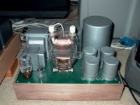
Yes...the 833 are doing a very easy job in my amp in compare with a RF transmitter.
The 833C have massive graphite anodes and these are glowing comlete after a hour, not a spot ony... 300W continous power per tube.
Decoupling the DC with a capacitor from the OPT is known as "parafeed OPT" since many years...you will find a lot about it.
The problem is a capacitor with 50uF/5kV. Because the bias current the OTP for single endet are gigantic for higher power amplifiers and they must have a core gap for suppressig the magnetical saturation.
Matthias
Yes...the 833 are doing a very easy job in my amp in compare with a RF transmitter
. The 833C have massive graphite anodes and these are glowing comlete after a hour, not a spot ony...
300W continous power per tube.Decoupling the DC with a capacitor from the OPT is known as "parafeed OPT" since many years...you will find a lot about it.
The problem is a capacitor with 50uF/5kV
. Because the bias current the OTP for single endet are gigantic for higher power amplifiers and they must have a core gap for suppressig the magnetical saturation.Matthias
@Magz
You are right... there is a lot of "Vooodooo" around Cords and cables...But I think a wire is a wire...no more...
But I thinkk also, every weight on copper and iron you use in the OPT is better than mgrams of Gold you are use in power Cords...
Matthias.
PS: because I'm a newbe here, it needs a lot of time, my Posts are shown....please admin, I 'm a newbee, but my Posts are all ok... so please, let me post! In nearly realtimeme...
Hi , with a proper designed line- in and output stages an ordinary twisted pair phone wire will give a good performance.
What do you guess how the signals from a broadcast studio gets to the transmitting site? Via Telephone line !
So its also my opinion, a wire is a wire nothing more.
73
Wolfgang
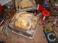
Each complete core (per channel) weighs 14.2kg. Then add in the wire, steel can, potting epoxy, etc.
Hi Magz,
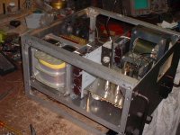
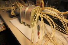
I wound two transformer for my hombrew projects. They are similar in size and weight. The measure of them are 170x170x150mm and the ready to fit weight is abt. 14 kg ( 31 lbs) . They are SE170a double C-cores . I salvaged the cores from a wrecked Siemens HF Transmitter.
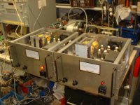
I made two clones of the MC-3500 McIntosh power amps with these trafos.
Below you´ll find some pics of the amps and the trafos. Believe me or not I need a whole weeks to wound ,wired and test them.
One amp deliver 400W rms. The Plate voltage is 470V .
The measures are:
width: 19"
hight: 6 units (10.5")
deepth: 16,5"
The total weight of one finished amp is 55kg ( 121 lbs)
Good luck with your project and be careful when working on high Voltage.
73
Wolfgang
Attachments
Parafeed caps
The parafeed cap shouldn't be that big. I use a 4uF/700V cap in my parafeed KT88 amps and will be using a 4uF/1500V cap for the parafeed 813 amps. My friend Reinout uses 4uF as well in his parafeed 833. the value depends on the primary impedance of the opt, not the secondary. Look for the 'where are the 833 amps' thread here for details (not to mention impressive pictures)
Decoupling the DC with a capacitor from the OPT is known as "parafeed OPT" since many years...you will find a lot about it.
The problem is a capacitor with 50uF/5kV
The parafeed cap shouldn't be that big. I use a 4uF/700V cap in my parafeed KT88 amps and will be using a 4uF/1500V cap for the parafeed 813 amps. My friend Reinout uses 4uF as well in his parafeed 833. the value depends on the primary impedance of the opt, not the secondary. Look for the 'where are the 833 amps' thread here for details (not to mention impressive pictures
)813 Plate Voltages
Hi Wolfgang,
Very impressive transformers. Did I understand you correctly ? the Plate Voltage on the 813's will only be 470 Volts ????.....
Hi Wolfgang,
Very impressive transformers. Did I understand you correctly ? the Plate Voltage on the 813's will only be 470 Volts ????.....
Hi Magz,
I wound two transformer for my hombrew projects. They are similar in size and weight. The measure of them are 170x170x150mm and the ready to fit weight is abt. 14 kg ( 31 lbs) . They are SE170a double C-cores . I salvaged the cores from a wrecked Siemens HF Transmitter.
I made two clones of the MC-3500 McIntosh power amps with these trafos.
Below you´ll find some pics of the amps and the trafos. Believe me or not I need a whole weeks to wound ,wired and test them.
One amp deliver 400W rms. The Plate voltage is 470V .
The measures are:
width: 19"
hight: 6 units (10.5")
deepth: 16,5"
The total weight of one finished amp is 55kg ( 121 lbs)
Good luck with your project and be careful when working on high Voltage.
73
Wolfgang
Hi,
The output tubes in my amps are the russian 6p45s, which is nearly identical to the the european EL519.
McIntosh used eight pcs. of the 6JE6 in their MC-3500 amps.
The 813 is a high voltage transmitting pentode, I still have three of them between my odds and ends. But I wouldn´t build anything with them. I will keep them as spare for existing equipment.
But I drifting away from this thread, because this one is about single ended amps with huge transmitting valves.
But anyway, those kinds of opts, working with several thousand volts, are masterpieces of the trafo winders trade.
I like to wind my own trafos.
If you want more about my homebrew project look at this:
http://www.diyaudio.com/forums/tubes-valves/139241-mcintosh-mc-3500-schematic-information.html
73
Wolfgang
Very impressive transformers. Did I understand you correctly ? the Plate Voltage on the 813's will only be 470 Volts ????.....
The output tubes in my amps are the russian 6p45s, which is nearly identical to the the european EL519.
McIntosh used eight pcs. of the 6JE6 in their MC-3500 amps.
The 813 is a high voltage transmitting pentode, I still have three of them between my odds and ends. But I wouldn´t build anything with them. I will keep them as spare for existing equipment.
But I drifting away from this thread, because this one is about single ended amps with huge transmitting valves.
But anyway, those kinds of opts, working with several thousand volts, are masterpieces of the trafo winders trade.
I like to wind my own trafos.
If you want more about my homebrew project look at this:
http://www.diyaudio.com/forums/tubes-valves/139241-mcintosh-mc-3500-schematic-information.html
73
Wolfgang
Good morning Matthias..
<snip>
I haven't built a SE amplifier in a long time....my concern has been unbalanced DC in the output transformer primary, core saturation and resulting distortion. Since the single ended RF final is the "load" for the modulator in a broadcast transmitter, the DC current for the RF final runs through a high inductance choke, and the audio from the modulation transformer is coupled through a large value high voltage capacitor (to keep the DC out of the modulation transformer secondary). I wonder how taking the DC out of the output transformer primary and coupling with a choke and large value capacitor (i.e. 50 uF, 5 kV) would sound using the SE output transformer? Anyone tried this?
As another posted, but aimed at the wrong poster, it's called "parafeed" in audio. Essentially Heising modulation for you.
_-_-
Back to the 833C amp.
I've been mulling over what protection scheme to use for the HV circuit in the amp.
What I've settled on is an 8A slow blow fuse for the mains, arrived at as follows:
3.33A draw for the Hammond 733A at idle (160mA x 2500/120)
1.155A draw for the Hammond 369KX at max power with full grid current
1.5A draw for the 833 filament circuit
Total = 5.985A. Multiply X 1.25 = 7.48A, round up to 8A slo-blo fuse.
Since the Hammond 733A power transformer is rated at 450mA ICAS, the 8A fuse should be plenty of protection as it will blow at ~257mA of B+ current, which is still well within the rating of the transformer. Even if the other circuits are off, the 8A fuse will blow at 384mA from the 733A. This should protect the PT from rectifier shorts or capacitor shorts or the unlikely choke short without needing a separate fuse on the 733A PT.
The 8A fuse, however does not protect the OPT from a short in the 833C tube, which could discharge the main reservoir caps and their 335 joules of energy through the OPT. For that I'll add a 5kV, 800mA microwave oven fuse in line between the last cap and the OPT.
That takes care of over-current situations, I think. Comments?
.
Last edited:
Hi Magz,
I'm using 8A slow blows at the mains also. I was trying 6.3A too, but they were blowing somtimes on switching on the B+. (I have switches for the filament and the B+, so I switch on the filament first and when the 833 are glowing, I switch on the B+. It is impossible to switch on the B+ without power up the filament first...) When I switch on the B+ both channels at the same time the main fuse 16A blows! So I have to switch on one by one...
But in Germany we use 230V at the mains!
The problem is the large capacity in my power supply.
I'm using a CLC circuit with 3x1000uF serial = 330uF, inductor 10H/500mA and 3 x 3300uF= 1100uF serial at the end. This mass of capacity is like a short curcuit when you switch on. . I did'nt calculate the reservoir in Joules, but I think you will have the same problem...an empty cap is like a short circuit...may be the fuse is slow enougth....may be not....
Because I like simple solutions I have added two 15Ohm resistors in front of the rectifier, so the current is limited at start up. You could also use a timer and a relais to bridge a serial resistor after startup (charging the caps)...but this is not the simple way.
Why I use so much capacity?
If it is up and runnig it's rock solid with no hum. I don't want to modulate the powerline of my provider...I want to modulate my OPT...
To use a microwave oven fuse is a great idea for this voltage... my B+ is about 1kV only, so I use normal glas fuses (500mA/fast) only and another one (100mA/fast) for the driver stage.
Matthias.
I'm using 8A slow blows at the mains also. I was trying 6.3A too, but they were blowing somtimes on switching on the B+
. (I have switches for the filament and the B+, so I switch on the filament first and when the 833 are glowing, I switch on the B+. It is impossible to switch on the B+ without power up the filament first...) When I switch on the B+ both channels at the same time the main fuse 16A blows! So I have to switch on one by one...But in Germany we use 230V at the mains!
The problem is the large capacity in my power supply.
I'm using a CLC circuit with 3x1000uF serial = 330uF, inductor 10H/500mA and 3 x 3300uF= 1100uF serial at the end. This mass of capacity is like a short curcuit when you switch on.
. I did'nt calculate the reservoir in Joules, but I think you will have the same problem...an empty cap is like a short circuit...may be the fuse is slow enougth....may be not....Because I like simple solutions I have added two 15Ohm resistors in front of the rectifier, so the current is limited at start up. You could also use a timer and a relais to bridge a serial resistor after startup (charging the caps)...but this is not the simple way
.Why I use so much capacity?
If it is up and runnig it's rock solid with no hum. I don't want to modulate the powerline of my provider...I want to modulate my OPT
...To use a microwave oven fuse is a great idea for this voltage... my B+ is about 1kV only, so I use normal glas fuses (500mA/fast) only and another one (100mA/fast) for the driver stage.
Matthias.
GM70 amp....60 watts for GM70 filament and 1000v @90 mA = 90 watts for GM70
I manage to get this going with a 3 amp slo blo.
Start Gm70 filament first then 15 second delay for B+. Using an inrush current limiter on the B+ transformer. My B+ transformer is only 237VA and no way it would start into a 3 amp slo blo without a pretty heavy in rush current limiter on the primary. Magz you have a 750 VA transformer...going to have a good kick to it!
- Home
- Amplifiers
- Tubes / Valves
- The Midlife Crisis - My 833C Amp Build