You use a 1k grid stopper?
I was a little mistaken on how I described the connections. There was a 470k from signal to ground and 47k from signal to tube. I ended up removing the 47k and using the 470k as the grid stopper. I then added a .1uf cap from signal to grid. This eliminated one carbon resistor from the audio path and also decouples the input.
Should there be a resistor from input to ground to provide some impedance for the line-level source?
Last edited:
You use a 1k grid stopper?
I was a little mistaken on how I described the connections. There was a 470k from signal to ground and 47k from signal to tube. I ended up removing the 47k and using the 470k as the grid stopper. I then added a .1uf cap from signal to grid. This eliminated one carbon resistor from the audio path and also decouples the input.
Should there be a resistor from input to ground to provide some impedance for the line-level source?
Such a large grid stopper is not needed and normally is undesirable. 1-10k is usually fine. YES, you NEED a resistance from grid to ground so that the grid has a ground reference. The maximum allowable value will be stated in the tube datasheet. Also, the grid stopper resistor should be mounted AS CLOSE AS PHYSICALLY POSSIBLE to the grid pin. HTH
I understand I need the grid resistor. As I mentioned, I decoupled the input with a .1uf cap and I used a 470k grid stopper. I asked about a resistor from INPUT to ground. Meaning source input before anything else.
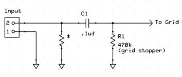
Here's a schematic with the proposed resistor marked with an asterisk. If you say 1k is an acceptable input impedance (when not using a capacitor) then 1k may be suitable here. If I lower the grid stopper to 1k I'll need to increase the capacitor as well.
You'll have to pardon my not knowing something that may seem obvious. In most of my other tube amps I use a 1meg grid stopper but those are instrument amplifiers.
Attachments
I'm measuring a small DC voltage coming from my computers sound card or maybe a ground loop? I figured the cap would eliminate any risk of DC.
I removed the single 100ohm output cathode resistor and installed two 200ohm 5w resistors (one per channel) along with a bypass cap but I have 13v on the 6BQ5 output tube cathodes. Is that ok or too much? Schematic calls for 11v.
Also, can anyone tell me what amps are in a Magnavox model 1RP625?
I removed the single 100ohm output cathode resistor and installed two 200ohm 5w resistors (one per channel) along with a bypass cap but I have 13v on the 6BQ5 output tube cathodes. Is that ok or too much? Schematic calls for 11v.
Also, can anyone tell me what amps are in a Magnavox model 1RP625?
Last edited:
The more I mod this amp the more I wish I left it alone. It seems to be loosing the "fullness" it had with the 45yr old components in it. It still sounds great but it seems like the treble is getting harsh yet very "twinkly", the mid-range is thin, but the base is much better then when I started. I used all poly-film capacitors with .1 and .047 between stages as the mod schematic recommended. Could the 13v bias on the outputs be causing this? I even replaced the crossover caps in the speakers just in case they were the cause. No change.
A closed hi-hat almost hurts at high volume. But the bass... THE BASS!! It's so smooth and buttery.
A closed hi-hat almost hurts at high volume. But the bass... THE BASS!! It's so smooth and buttery.
Last edited:
There seems to be some confusion with terminology. The grid stopper resistor is the one connected in series with the grid (47k on the original circuit, 1k suggested by others), and is there to stop HF oscillation, it should be soldered directly to the tube socket. The 470k resistor from grid to ground is the grid leak resistor. If you want the input capacitor, I don't think it is necessary to have the resistor with the star in your diagram. So you would have input to 0.1 uF capacitor, then 470k resistor to ground, then 1k resistor in series to grid.
I understand I need the grid resistor. As I mentioned, I decoupled the input with a .1uf cap and I used a 470k grid stopper. I asked about a resistor from INPUT to ground. Meaning source input before anything else.
Here's a schematic with the proposed resistor marked with an asterisk. If you say 1k is an acceptable input impedance (when not using a capacitor) then 1k may be suitable here. If I lower the grid stopper to 1k I'll need to increase the capacitor as well.
You'll have to pardon my not knowing something that may seem obvious. In most of my other tube amps I use a 1meg grid stopper but those are instrument amplifiers.
Ok, terminology is the problem here... in your drawing the 470k resistor from GRID TO GROUND is NOT a grid "stopper" resistor. A grid stopper resistor is a resistor is in series with the grid and prevents oscillation by forming a low pass filter. Your 470k resistor is often called a "grid resistor" and provides a ground reference for the tubes grid.
Refer please to the original schematic where a 47k resistor was in SERIES with the grid and a 470k resistor was from GRID TO GROUND. A capacitor in SERIES should not be needed.
To clarify; in your drawing there does not need to be a resistor to ground before the cap, there needs to be a resistor IN SERIES with the grid "a grid stopper" to "stop oscillations or the chance thereof, and a resistor to ground ( known as a grid resistor) to provide a dc ground reference for the tubes grid. A cap should not be needed. The grid to ground resistor comes BEFORE the "grid stopper" resistor which is the last thing in line with the tubes grid. I can refer you to a few schematics if that is not clear... HTH
Thank you guys. I now understand what the 47k resistor was. I was incorrectly visualizing it as a voltage divider with the 470k. Since I was after more gain it made sense to remove it but now I see that would do nothing. I'll insert a 1k in it's place when I can.
At the moment I have it wired as shown above. I installed a 10k for the * resistor and that made a world of difference. It may have to do with my line source. I have been using the on-board audio of a cheap computer and listening to 320k streams. Half of these Shoutcast channels need their "engineer" dragged behind the shed and beat with a.... I digress. With the 10k in place I have my imaging back and mids toned down quite a bit. I just can't explain why so I'll blame the sound card.
I plan to replace the sockets, filter caps, and swap all the resistors out for metal film. I'd also like to transfer it into a more compact chassis in the process. This will become the amp for my computer monitors which are just Wharfedale Diamond 8.1 but they play nicely this amp.
Next, I'm hell-bent on finding a pair of the Magnavox bi-amp modules used in the Concert Grand consoles. I hear they are hard to find. I accept the challenge. Good thing I live in an area with a dozen church rummage sales and even more antique/thrift/resale stores.
"ext, I'm hell-bent on finding a pair of the Magnavox bi-amp modules used in the Concert Grand consoles. I hear they are hard to find. I accept the challenge. Good thing I live in an area with a dozen church rummage sales and even more antique/thrift/resale stores."
I think I have one, it is a 6v6 PP for the low end and el84 se for the highs, the output trannys for the high end are extremely small. I re capped it last month, so now I am just waiting on some time to make the original wiring safer before I fire it up.
I think I have one, it is a 6v6 PP for the low end and el84 se for the highs, the output trannys for the high end are extremely small. I re capped it last month, so now I am just waiting on some time to make the original wiring safer before I fire it up.
"ext, I'm hell-bent on finding a pair of the Magnavox bi-amp modules used in the Concert Grand consoles. I hear they are hard to find. I accept the challenge. Good thing I live in an area with a dozen church rummage sales and even more antique/thrift/resale stores."
I think I have one, it is a 6v6 PP for the low end and el84 se for the highs, the output trannys for the high end are extremely small. I re capped it last month, so now I am just waiting on some time to make the original wiring safer before I fire it up.
I'm not sure that's the one. I'm looking for the one with six 6v6 for lows and two 6v6 for highs. Post pics.
As for my maggie... To verify, I found an SB Audigy soundcard kicking around and threw that in the computer. Set it to 24bit/96k. Sounds very well balanced now. It was the soundcard after all. My mids are nice and soft. The piano doesn't reach out and punch me in the face anymore. Female vocals sound great. Bass is warm and full. Strings breathe. I'm content.
 And this is all through those Zenith speakers. I'm impressed they sound as good as they do.
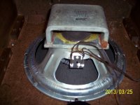
Check out the alnico on that 10in. Yes, 10in. That magnet makes it look like a 6in or 8in.
Attachments
Last edited:
I bought a NuForce dac for my computer, it was a major improvement over the sound cards.
I've seen pictures of the 6 6V6 maggie amps, mine is much smaller.
I have a nice collection of old speakers, way more then I'll ever use, just could never toss any when I was picking up and buying consoles. Some of them sound very good.
I've seen pictures of the 6 6V6 maggie amps, mine is much smaller.
I have a nice collection of old speakers, way more then I'll ever use, just could never toss any when I was picking up and buying consoles. Some of them sound very good.
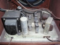
In another thread I mentioned this Motorola 6BQ5 amp I picked up (pic below). I have it up and running and it sounds pretty good. Has massive transformers for only being a quad of 6BQ5s and a pair of 12AX7s. I'm much happier with the low-end of this amp but the Magnavox has more airiness to it. I can't find a schematic for the Motorola so I'll try and make one unless anyone has it. Chassis model is HS-711A.

Attachments
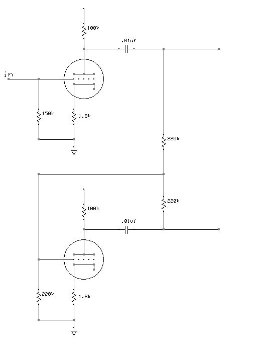
The Motorola has a paraphrase invertor but I haven't seen one like this before. It looks like they use negative feedback from the invertor to adjust it's gain. I usually just see paraphase invertors uses a resistor divider to adjust the gain. Motorola's method makes for a simple parts list.
Is there a benefit to this method? Would it help to prevent or create distortion caused by the PI?
Is there a benefit to this method? Would it help to prevent or create distortion caused by the PI?
Attachments

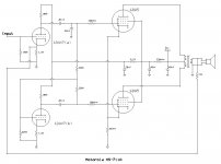
I don't see a phase compensating cap. in parallel with the 15 KOhm NFB resistor. If you have an o'scope and signal generator, you can play with 2 KHz. square waves to get a reasonable compensating cap. value.
It's not in Motorola's design. I did just add a missing 22pf cap off the preamp.
- Status
- This old topic is closed. If you want to reopen this topic, contact a moderator using the "Report Post" button.
- Home
- Amplifiers
- Tubes / Valves
- Found myself a Magnavox 9302-00