Hello,
Some time ago, Rod Coleman suggested using a CCS to obtain a clean fixed bias by generating a voltage drop on the grid resistor - the bias power supply and its capacitors are isolated by the constant current sink and are no longer in the signal path.
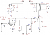
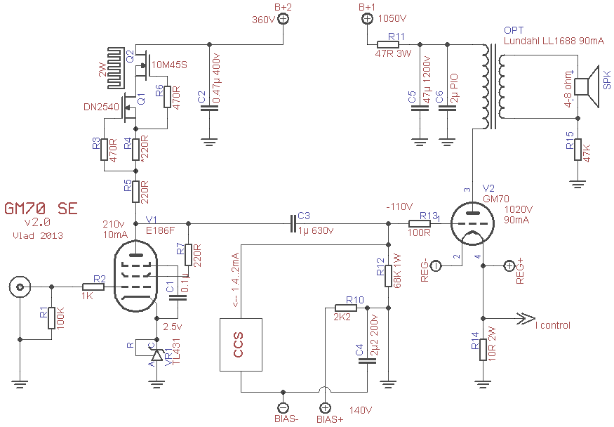
Great idea! I tried it in my R-C coupled GM70 SE amplifier. The schematic is below.
The bias PSU is well filtered by a MOSfet follower buffered voltage reference, and I tried two different constant current sinks: a cascoded, LED biased bipolar junction transistor CCS, and a 10M45S-DN2540 Mosfet cascode (which works down to 0.5mA current. A DN2540-DN2540 cascode couldn't go below 5.5mA in my tests).
The result - well, this CCS bias definitely sounds better to me than the classic fixed bias! I was very happy, until I checked the signal on the scope...
The negative going swing has its top soft-clipped!!!!! This only occurs after 18v peak swing with the BJT CCS and after 40v peak with the depletion mode MOSfet CCS. I hadn't heard the distortion because I only listened at a reasonable power level - I have sensitive speakers and neighbours...
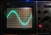
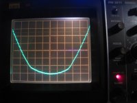
Please see the oscillograms below. It's not a hard clipping, the waveform distortion appears at a certain level and remains quite the same up to the maximum swing (120v peak with D3a).
I can't figure this one out - what is causing this distortion and ruining a promising bias topology? (note: everything works perfectly with the classic fixed bias. The load is a 68K resistor as shown in the schematic.)
Some time ago, Rod Coleman suggested using a CCS to obtain a clean fixed bias by generating a voltage drop on the grid resistor - the bias power supply and its capacitors are isolated by the constant current sink and are no longer in the signal path.
Great idea! I tried it in my R-C coupled GM70 SE amplifier. The schematic is below.
The bias PSU is well filtered by a MOSfet follower buffered voltage reference, and I tried two different constant current sinks: a cascoded, LED biased bipolar junction transistor CCS, and a 10M45S-DN2540 Mosfet cascode (which works down to 0.5mA current. A DN2540-DN2540 cascode couldn't go below 5.5mA in my tests).
The result - well, this CCS bias definitely sounds better to me than the classic fixed bias! I was very happy, until I checked the signal on the scope...
The negative going swing has its top soft-clipped!!!!!
This only occurs after 18v peak swing with the BJT CCS and after 40v peak with the depletion mode MOSfet CCS. I hadn't heard the distortion because I only listened at a reasonable power level - I have sensitive speakers and neighbours...Please see the oscillograms below. It's not a hard clipping, the waveform distortion appears at a certain level and remains quite the same up to the maximum swing (120v peak with D3a).
I can't figure this one out - what is causing this distortion and ruining a promising bias topology? (note: everything works perfectly with the classic fixed bias. The load is a 68K resistor as shown in the schematic.)
Attachments
 The power of small talk.
Not much signal gets to return through bias network caps, unless the bias resistor is unusually low in value. In any case, a typical cap is nearer to being an ideal capacitor than a typical CCS is to an ideal CCS. The other end of the CCS also needs a negative voltage supply of about twice the value needed for the normal voltage bias.
Most CCS have a limited voltage range, beyond which they can act as a clamp (i.e. voltage source). However, even given a perfect CCS I can't see any real advantage. Much better to have a voltage source at the other end of the grid resistor.
Most CCS have a limited voltage range, beyond which they can act as a clamp (i.e. voltage source). However, even given a perfect CCS I can't see any real advantage. Much better to have a voltage source at the other end of the grid resistor.
In what sense is it an advantage to add a (necessarily imperfect) CCS in parallel with the 'signal path' instead of merely having a low impedance voltage supply at the other end of the grid resistor? As you have found, it makes things worse.
Actually it made things better... until it ran out of headroom, because of my own flawed design.
The advantage is, as SemperFi said, that the CCS has a very high impedance (tens of Mohm) at audio frequencies, and the signal no longer returns via the bias supply capacitors.
(another good fixed bias solution would be a shunt regulator like Salas' SSHV, I think... )
I would worry a lot more about a CCS (right at the signal) than a bias supply cap (remote from the signal). Remember, passive components are a lot closer to ideal than any active component. Those who suffer from faradophobia have, like all phobics, to add unnecessary complications to their lives in order to avoid the feared object. Even a nasty bias cap will produce very little distortion at the valve grid because of the low output impedance of the previous stage.
Straining at gnats; swallowing camels.
Straining at gnats; swallowing camels.
Well,
basically you need a (stable) voltage source for bias. This can be made directly by a (regulated) bias voltage supply.
In principle, the approach via current should work as well: Creating a constant current source and letting it work into a (constant) resistance should give a stable voltage across that resistance.
Question IMHO is: What is easier and more 'ideal' to build? A voltage regulator or a constant current source?
Rundmaus
I would worry a lot more about a CCS (right at the signal) than a bias supply cap (remote from the signal).
Hello,
The signal can't go through the CCS, but it *does* return through the bias supply capacitor.
Remember, passive components are a lot closer to ideal than any active component. Those who suffer from faradophobia have, like all phobics, to add unnecessary complications to their lives in order to avoid the feared object. Even a nasty bias cap will produce very little distortion at the valve grid because of the low output impedance of the previous stage.
Erm... my ears tell me otherwise.
You can call me a faradophobic, but there is a reason I avoid capacitors - every time that I manage to get one out of the equation, the sound improves (you will probably dismiss that as "psychoacoustics", but I'm quite sure of what I hear).
Unless your CCS is perfect, signal current does go through it. Some of this current will go through non-linear junction capacitances. Any voltage imperfection is presented straight at the output grid.
I'm pleased that you are sure what you hear. It must be nice to have superhuman powers. The rest of us will just have to put up with our misleading ears and misleading brains, and just trust circuit theory etc. to help us on our way to good sound.
I'm pleased that you are sure what you hear. It must be nice to have superhuman powers. The rest of us will just have to put up with our misleading ears and misleading brains, and just trust circuit theory etc. to help us on our way to good sound.
The CCS pulls the grid down to the bias voltage -110V. The signal sees only the 68kohm resistor and return path is only thru that. (relatively speaking here, of course the CCS isnt ideal in real life, but the non-ideals are perhaps small enough to ignore...) With a fixed negative voltage, the signal also only sees the 68kohm resistor, but return path is back around thru the caps in the bias supply.
Unless your CCS is perfect, signal current does go through it. Some of this current will go through non-linear junction capacitances. Any voltage imperfection is presented straight at the output grid.
I'm pleased that you are sure what you hear. It must be nice to have superhuman powers. The rest of us will just have to put up with our misleading ears and misleading brains, and just trust circuit theory etc. to help us on our way to good sound.
How much capacitance do you think there is here? We're talking a CCS sinking a few mA. Unless he's using a monster transitor there really isn't much to talk about. As long as there's > 10V over the transistor the capacitances are pretty low. I agree in this case the CCS will see a large voltage swing, but how non-linear is the capacitance over most of it? I can see it be no problem except near the extremes.
I havent tried this bias method yet, but what's so wrong in trying something new? Isolating PSU ripple from the b+ by using a CCS is well known to work wonders, much like a choke. Perhaps this does something you cannot understand. Untill you've tried it you can at least be a little less harsh and either not post a reply, or be positive and try to learn something new.
Let's take a wild guess that the CCS has 10pF of (mainly) non-linear capacitance. At 20kHz this is about 800k reactance, so about 8% of the signal current goes through here. Whatever distortion is caused will be attenuated by the source impedance of the previous stage: Rs seen from an 800k impedance. So distortion will be something like 0.08 x Rs/800k x CCSd = 10^(-7) x Rs x CCSd.
Now consider the more normal voltage bias. Take a wild guess that the bias decoupling cap is 10uF. At 20Hz that has a reactance of 800 ohms, so the signal voltage across it will be about 1.2%. Any distortion generated here will be further reduced on its way back, by a factor of 68k/Rs. So distortion will be something like 0.012 x Rs/68k x CAPd = 1.7 x 10^(-7) x Rs x CAPd.
So both have, on the face of it, similar levels of distortion except one is worse at LF and the other is worse at HF. However, my guess is that a CCS parasitic capacitance is far more non-linear than a capacitor. So I think the conventional circuit wins.
I assume others have done similar estimates and come to different conclusions? Or is your uncalculated preference for this circuit somehow superior to my numeric doubts? Without numbers all we have is opinions. Of course, the grid bias CCS is in parallel with the anode load CCS in the previous stage so you could argue that the worse it could do is double whatever CCS distortion there is, but the anode one probably has more quiescent voltage across it so will probably distort less.
So both have, on the face of it, similar levels of distortion..... However, my guess is ...... So I think.....
Or is your uncalculated preference for this circuit somehow superior to my numeric doubts? Without numbers all we have is opinions. Of course, the grid bias CCS is in parallel with the anode load CCS in the previous stage so you could argue that the worse it could do is double whatever CCS distortion there is, but the anode one probably has more quiescent voltage across it so will probably distort less.
Since you dont have any hard facts either I wonder why you are so belligerent to the OP. I said I havent tried this myself, and may or may not in the future. I just dont think you have any reasons to tell the OP he has 'super ears' etc when you dont even know how this bias ckt sounds. Even your high level calculations couldn't come up with any astounding cons or pros.
Perhaps it cancels the anode CCS distortions preceding it...
So basically you want to say to all the forumites here that use gyrators and CCS loadings on their plates that they are either not listening correctly or that they have super hearing. Normal folks like you will never hear the benefits they all proclaim and since they cant give you numbers you'll never waste your time contemplating such designs. Good on you.
Some of us use gyrators and CCS because of clear, quantitative, measurable advantages. Dave's complaint is that this circuit doesn't seem to have any. I can't see any myself, but if you (or anyone else) wants to show these advantages theoretically or experimentally, we're all ears, so to speak.
I expressed an opinion, contrary to others. Are contrary opinions not welcome? So far this thread is short on facts. I attempted to rectify this.
Read what I said, including about anode CCS. Don't criticise me for what I didn't say.
A bias circuit should not 'sound'. 'Belligerent' means hostile and aggressive; I have been neither, merely contrary. If rejecting anecdotes is regarded as hostility then no meaningful discussion about audio electronics is possible.
- Status
- This old topic is closed. If you want to reopen this topic, contact a moderator using the "Report Post" button.
- Home
- Amplifiers
- Tubes / Valves
- CCS fixed bias