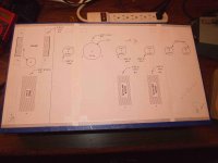
Just starting a buildup of yet another TunelabSE.
Pretty much straight from the original design, 12AX7 input tubes and 6L6 power tubes. I opted to go for point-to-point wiring in order to change the tube placement, and I am also going to use two 12AX7 tubes on the input (one per channel) to keep the 2nd triode in each tube "available" for experimenting (should I ever get the urge, time, etc.)
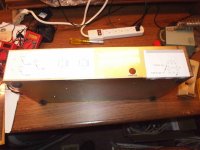
I'm calling it the "Nabu", after the chassis I picked up to build this in. In my search for something that would look reasonably decent, and be reasonably inexpensive, I stumbled across a source for some old NABU computer boxes.
The story on this system is interesting, it was an internet-type cable system developed in Canada back in the early 1980's - well before the "real" internet came into general usage.
The system interfaced to a regular television screen, and was intended to offer information, news, and online marketplaces. Very similar to the Internet of today, except without the nice graphics.
Unfortunately, the system was WAY ahead of its time and did not catch on.
The good thing (for hobby folks, anyway) is that these boxes were surplused off, many of them in original boxes that were never opened! The cabinets are steel, have a nice charcoal-pebble finish, and come with all of the innards still inside - transformer, a couple of regulators (5V, 8V) a processor board with lots of old 74xx series TTL (DIPS, not those invisible SMT things...) and an RF receiver/modulator.
It's mostly junk, but hey - for the same price (including shipping) as a 17x10 Hammond plain-box... I'll take the extra junk!
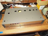
I have limited woodworking skills, and could never hope to craft some of the beautiful cabinets I see here. So I will take the easy way out and purchase something (cheep!) that I can just punch holes in.
The box is 18" x 10" x 3", and the top cover comes off to reveal a chassis with an internal wall - perfect for isolating the power supply choke!
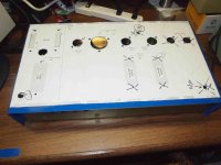
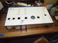
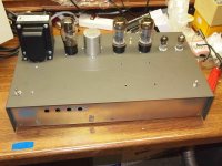
I've mounted the choke and OPTs inside, the rest of the stuff goes on top.
The wiring begins next, and I am really excited about getting this design up and running.
~ Sam
Pretty much straight from the original design, 12AX7 input tubes and 6L6 power tubes. I opted to go for point-to-point wiring in order to change the tube placement, and I am also going to use two 12AX7 tubes on the input (one per channel) to keep the 2nd triode in each tube "available" for experimenting (should I ever get the urge, time, etc.)
I'm calling it the "Nabu", after the chassis I picked up to build this in. In my search for something that would look reasonably decent, and be reasonably inexpensive, I stumbled across a source for some old NABU computer boxes.
The story on this system is interesting, it was an internet-type cable system developed in Canada back in the early 1980's - well before the "real" internet came into general usage.
The system interfaced to a regular television screen, and was intended to offer information, news, and online marketplaces. Very similar to the Internet of today, except without the nice graphics.
Unfortunately, the system was WAY ahead of its time and did not catch on.
The good thing (for hobby folks, anyway) is that these boxes were surplused off, many of them in original boxes that were never opened! The cabinets are steel, have a nice charcoal-pebble finish, and come with all of the innards still inside - transformer, a couple of regulators (5V, 8V) a processor board with lots of old 74xx series TTL (DIPS, not those invisible SMT things...) and an RF receiver/modulator.
It's mostly junk, but hey - for the same price (including shipping) as a 17x10 Hammond plain-box... I'll take the extra junk!
I have limited woodworking skills, and could never hope to craft some of the beautiful cabinets I see here. So I will take the easy way out and purchase something (cheep!) that I can just punch holes in.
The box is 18" x 10" x 3", and the top cover comes off to reveal a chassis with an internal wall - perfect for isolating the power supply choke!
I've mounted the choke and OPTs inside, the rest of the stuff goes on top.
The wiring begins next, and I am really excited about getting this design up and running.
~ Sam